Shell for condensing equipment

A technology for condensing equipment and casings, which is applied in the field of casings for condensing equipment, and can solve problems such as heat dissipation obstruction of condenser casings, condenser damage, troublesome operation, etc., so as to reduce the time for disassembling and assembling casings, improve efficiency, and facilitate maintenance and maintenance work Effect

Inactive Publication Date: 2021-11-30
义乌市今朝创意设计有限公司
View PDF0 Cites 0 Cited by
  • Summary
  • Abstract
  • Description
  • Claims
  • Application Information

AI Technical Summary

Problems solved by technology

[0003] The purpose of the present invention is to provide a casing for condensing equipment, which solves the problem that in the prior art, workers who accidentally approach the condenser will be burned due to the high temperature of the condenser, and will also cause certain damage to the condenser. If you directly install a The outer casing needs to be removed for repair and maintenance in the later period, so the operation is very troublesome and has certain safety hazards. At the same time, it solves the problem that the condenser casing has a certain hindering effect on heat dissipation.

Method used


Image

  • Shell for condensing equipment
  • Shell for condensing equipment
  • Shell for condensing equipment

Examples


no. 1 example

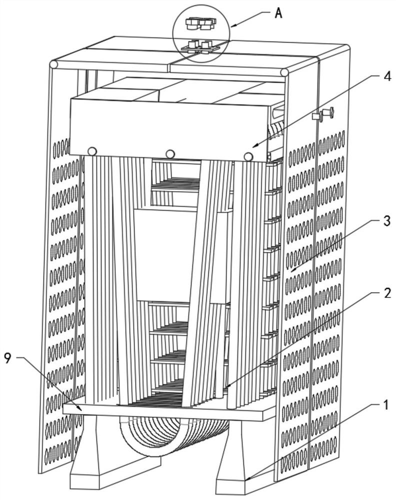
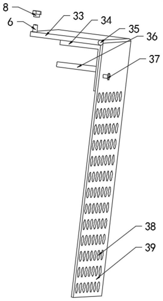
[0036] refer to Figure 1-4 , a shell for condensing equipment, including a condenser 2, a bottom plate 9 connected to the bottom of the condenser 2, support legs 1 connected to both sides of the bottom of the bottom plate 9, and both sides of the condenser 2 are connected with a protective mechanism 3 through a connecting mechanism 4, The protective mechanism 3 includes multiple sets of protective shells 39, one side of the protective shell 39 is provided with a top plate 33, and the top side of each top plate 33 is provided with a first screw 6, and the top plate 33 is rotationally connected with the protective shell 39 through a rotating shaft 35. The corresponding inboard of top plate 33 and protective shell 39 is provided with connecting rod 34, and the side view surface of connecting rod 34 is L-shaped, and one side of the vertical section of connecting rod 34 is connected with protective shell 39 bolts by second screw rod 37, connects The top of the horizontal section o...

no. 2 example

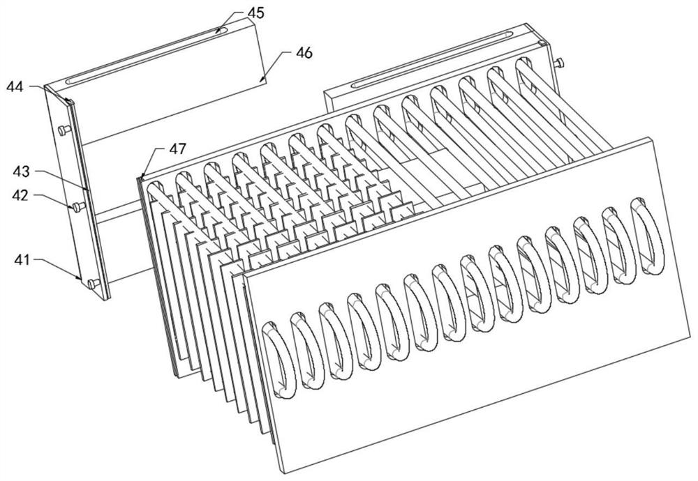
[0044] Based on the casing for condensing equipment provided in the first embodiment, the quick disassembly and assembly of the casing of the condensing equipment is realized, and the maintenance and replacement are convenient. However, in actual use, the casing is in close contact with the condenser 2, and the temperature of the casing will still rise accordingly. High, its own service durability will be greatly reduced, and workers can still cause damage to it when they accidentally touch the shell, and it is obviously not enough to achieve rapid heat dissipation only by ventilation holes 38 and natural wind. The efficiency is poor, let alone the specific heat dissipation treatment for specific parts, the adaptability is poor, and the fixed-point heat dissipation capability is poor. Figure 5-9 , this kind of condensing equipment shell also includes: the interior of the top plate 33 is provided with a heat dissipation fan 11, through the heat dissipation fan 11, the condenser...


PUM


Abstract

The invention relates to the technical field of condensers, in particular to a shell for condensing equipment. The shell comprises a condenser, and the two sides of the condenser are connected with protective mechanisms through a connecting mechanism; and each protection mechanism comprises multiple sets of protection shells, top plates are arranged at the tops of the protection shells, first screw rods are arranged on one sides of the tops of the top plates, cooling fans are arranged in the top plates, the top plates are rotationally connected with the protection shells through rotating shafts, connecting rods are arranged on the sides, corresponding to the protection shells, of the top plates, the side view faces of the connecting rods are in an L shape, and the tops of the horizontal sections of the connecting rods make contact with the top plates. According to the shell, the operation is convenient, the protection effect is good, the later maintenance work is convenient, the time for disassembling and assembling the shell is reduced, fixed-point heat dissipation can be realized, the heat dissipation efficiency is improved through feedback and negative feedback, the heat dissipation effect is ensured, resources are saved, the centralized and accurate utilization of the resources is ensured, rapid and efficient heat dissipation is realized, and the heat dissipation effect is greatly improved.

Description

technical field [0001] The invention relates to the technical field of condensers, in particular to a casing for condensing equipment. Background technique [0002] The condenser is a component of the refrigeration system and is a type of heat exchanger. It can convert gas or vapor into liquid, and transfer the heat in the tube to the air near the tube in a very fast manner. The working process of the condenser is an exothermic process, so the temperature of the condenser is relatively high. Power plants use many condensers to condense the exhaust steam from the turbines. Condensers are used in refrigeration plants to condense refrigerant vapors such as ammonia and freon. Condensers are used in the petrochemical industry to condense hydrocarbons and other chemical vapors. In the distillation process, the device that converts vapor into liquid state is also called condenser. All condensers operate by removing heat from a gas or vapor. However, most of the existing conden...

Claims


Application Information

Patent Timeline
Patent Type & Authority Applications(China)
IPC IPC(8): F25B39/04F28F1/32F28F9/00F28F9/26F28F27/00F16F15/067
CPCF25B39/04F28F9/002F28F1/32F28F9/26F28F27/00F16F15/067Y02B30/70Y02P20/10
Inventor 王国洪
Owner 义乌市今朝创意设计有限公司
Why Eureka
Try Eureka