
Low-output ripple boost rectifier and control method thereof

A control method and boost type technology, which are applied in the output power conversion device, the conversion of AC power input to DC power output, electrical components, etc. The effect of capacitance capacity and fast dynamic response

Active Publication Date: 2021-11-30
ANHUI UNIVERSITY OF TECHNOLOGY
View PDF13 Cites 0 Cited by
  • Summary
  • Abstract
  • Description
  • Claims
  • Application Information

AI Technical Summary

Problems solved by technology

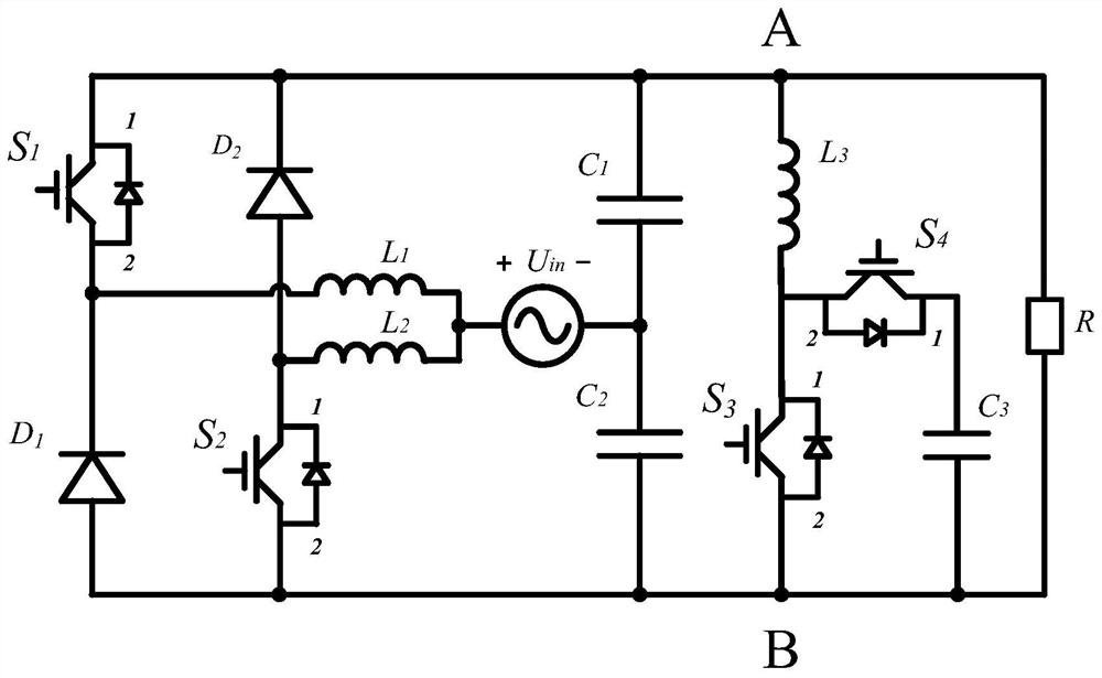
[0006] The object of the present invention is to provide a low-output ripple boost rectifier and its control method. The converter of the present invention can overcome the shortcomings of the bridge arm direct-connection hidden danger and the body diode of the switch tube participating in the work of the traditional bridge rectifier circuit, and can also Suppression of second harmonics in DC link voltage

Method used


Image

  • Low-output ripple boost rectifier and control method thereof
  • Low-output ripple boost rectifier and control method thereof
  • Low-output ripple boost rectifier and control method thereof

Examples


Embodiment 1

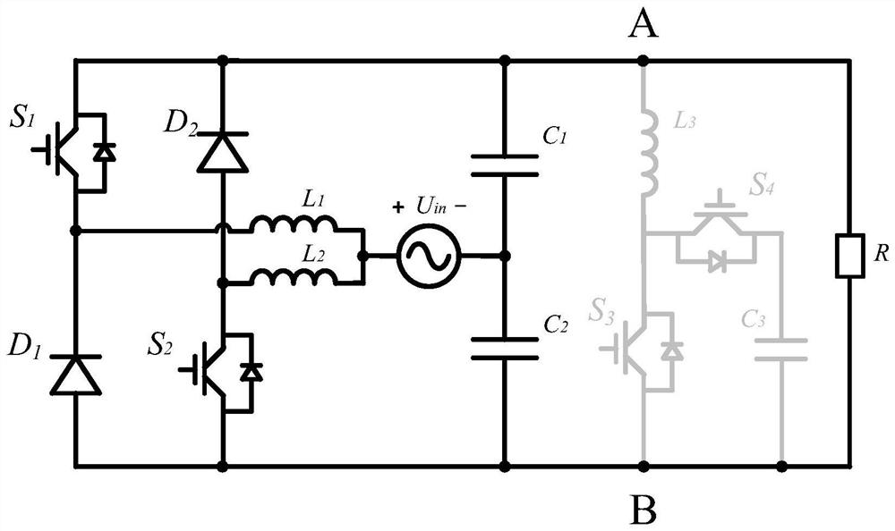
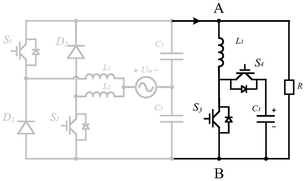
[0047] combine figure 1 and figure 2 , a low output ripple boost rectifier of this embodiment, its main circuit includes a power switch tube S 1 , S 2 , inductance L 1 , L 2 , capacitance C 1 、C 2 , Diode D 1 and D 2 ; AC power supply U in The reference positive terminal and the inductance L 1 and L 2 connected at one end, the inductance L 1 The other end of the diode D 1 connected to the cathode, the inductor L 2 The other end of the diode D 2 anode connected, the diode D 1 The anode is respectively connected to the power switch tube S 2 terminal 2, capacitor C 2 One end of the diode is connected to node B; diode D 2 The cathode is connected to the power switch tube S 1 Terminal 1, capacitor C 1 One end of the capacitor is connected to node A; capacitor C 1 and C 2 Connect the other end of the AC power supply U in The reference negative terminal; among them, the power switch tube S 1 , S 2 Anti-parallel diodes across both ends. Nodes A and B form the...


PUM


Abstract

The invention discloses a low-output ripple boost rectifier and a control method thereof, which belong to the technical field of power electronic converters. One end of L1 is connected with the positive end of Uin, and the other end is connected with S1; one end of L2 is connected with one end of Uin, and the other end of L2 is connected with S2; one end of L3 is connected with the cathode of D2, and the other end is connected with S4; the anode of the D1 is respectively connected with one ends of the S2, the S3, the capacitor C2 and the capacitor C3; the cathode of the D1 is respectively connected with one end of the L1 and the S1; the anode of the D2 is respectively connected with one ends of the S2 and the L2; the cathode of D2 is connected with one end of S1, one end of L3 and one end of C1. The rectifier disclosed by the invention belongs to an integrated rectifier, the multiplexing technology of a power device is utilized, the number of elements of the rectifier is remarkably reduced, the system cost is reduced, the integration level is improved, and the occupied space of a circuit is small; in the working process, no body diode of the power switch tube participates, the switching loss is small, the efficiency is high, the cost is low, and the service life is long.

Description

technical field [0001] The invention relates to the technical field of power electronic converters, in particular to a low output ripple step-up rectifier and a control method thereof. Background technique [0002] With the development of modern science and technology, the new energy industry is booming, and new energy needs to be converted into electrical energy for use in equipment. If the primary energy fails during the conversion into electrical energy, it will not only cause waste of resources, but also cause The power system and electrical equipment are damaged, so the reliability of power quality must be guaranteed. PWM rectification technology plays an important role in electric energy conversion. Therefore, it is of great practical significance to develop rectifiers with high efficiency, high reliability and high power density. [0003] The traditional PWM rectifier circuit is mainly based on bridge topology. Since two power switch tubes on a bridge arm are directl...

Claims


Application Information

Patent Timeline
Patent Type & Authority Applications(China)
IPC IPC(8): H02M7/217H02M1/14H02M1/32
CPCH02M7/217H02M1/14H02M1/32
Inventor 胡雪峰何天亚张乔穆坤输
Owner ANHUI UNIVERSITY OF TECHNOLOGY
Learn More