Direct-driven swing head air cooling system

A technology of air cooling and swinging head, which is applied in the direction of metal processing machinery parts, maintenance and safety accessories, measuring/indicating equipment, etc., and can solve the problems of reducing the machining accuracy of swinging head, cooling liquid backflow, and small cooling area of ​​direct drive swinging head, etc. , to achieve the effect of increasing the heat transfer range and heat transfer area, reducing the influence of thermal deformation, and avoiding slow cooling rate

Pending Publication Date: 2021-12-03
宁波天控五轴数控技术有限公司
View PDF0 Cites 1 Cited by
  • Summary
  • Abstract
  • Description
  • Claims
  • Application Information

AI Technical Summary

Problems solved by technology

Among them, the water circulation of the vertical circulation waterway structure is not good, and the phenomenon of coolant backflow is very easy to occur during the cooling process; the U-shaped guide tank waterway improves the right-angle elbow structure of the vertical circulation waterway, which solves the problem of coolant backflow, but the U-shaped The design of the waterway will cause uneven cooling area and poor cooling effect; the spiral waterway structure is a cooling method with better cooling effect in the prior art, but the cooling area of ​​the direct-drive swing head is cooled by liquid cooling, which has a great impact on the sealing technology. The requirements are high and the cooling effect of the components inside the direct drive swing head cannot be quickly achieved
At the same time, in the prior art, there are also deficiencies in the cooling temperature control of the direct-drive oscillating head, which cannot effectively control the cooling effect of the motor in real time, causing thermal displacement of the direct-drive oscillating head due to high temperature, reducing the swing head. Precision

Method used


Image

  • Direct-driven swing head air cooling system
  • Direct-driven swing head air cooling system
  • Direct-driven swing head air cooling system

Examples


Embodiment Construction

[0018] The technical solutions in the embodiments of the present invention will be clearly and completely described below with reference to the accompanying drawings in the embodiments of the present invention. Obviously, the described embodiments are only a part of the embodiments of the present invention, but not all of the embodiments. Based on the embodiments of the present invention, all other embodiments obtained by those of ordinary skill in the art without creative efforts shall fall within the protection scope of the present invention.

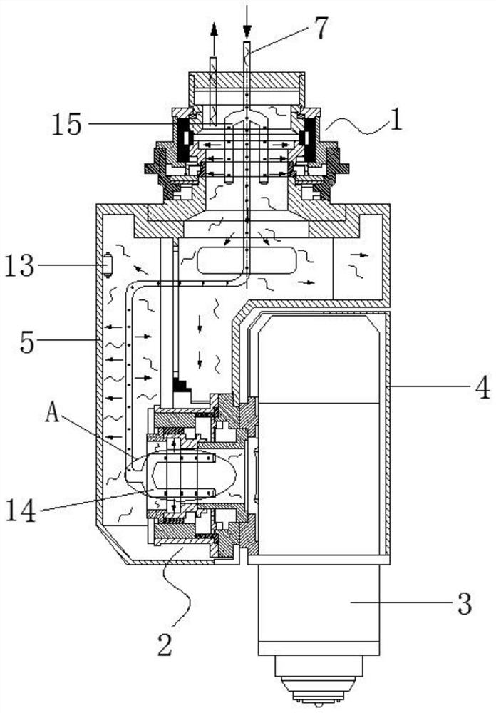
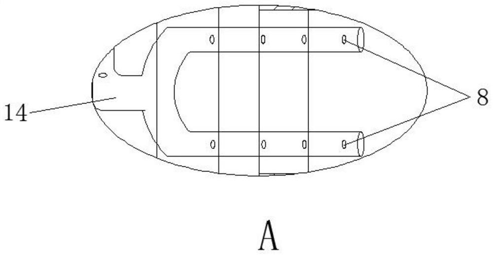
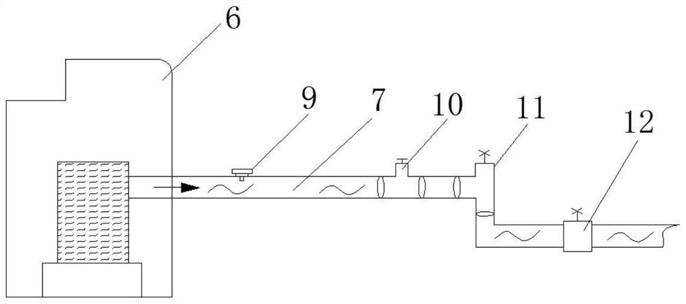
[0019] see Figure 1-3 , the embodiment of the present invention discloses a direct-drive swing head air cooling system, including: C-axis 1, A-axis 2, electric spindle 3, headstock 4, A-axis housing 5, air conditioner 6 and cooling pipeline 7, The electric spindle 3 is installed in the main shaft box 4, the A-axis 2 is installed inside the A-axis housing 5, the C-axis 1 and the A-axis 2 are both hollow structures, one end of the cool...


PUM


Abstract

The invention discloses a direct-drive swing head air cooling system, and relates to the technical field of direct-drive swing head cooling. The direct-drive swing head air cooling system comprises a C shaft, an A shaft, an electric spindle, a spindle box, an A shaft shell, an air conditioner and cooling pipelines, the electric spindle is installed in the spindle box, the A shaft is installed in the A shaft shell, the C shaft and the A shaft are both of a hollow structure, one ends of the cooling pipelines are connected with the air conditioner, the other ends of the cooling pipelines penetrate through the interior of the C shaft and extends into the A shaft from the interior of the A shaft shell, and air holes are formed in the portions, located in the C shaft, the A shaft and the spindle box, of the cooling pipelines. The cooling pipelines are arranged in the C shaft, the A shaft and the A shaft shell, and the air holes are formed in the cooling pipelines, so that parts in the C shaft, the A shaft and the A shaft shell can be rapidly cooled, the heat exchange range and the heat exchange area can be enlarged through arrangement of a first branch pipe and a second branch pipe, rapid cooling is facilitated, the heat dissipation efficiency is improved, and the thermal deformation influence is reduced.

Description

technical field [0001] The invention relates to the technical field of direct-drive swing head cooling, and more particularly to a direct-drive swing head air cooling system. Background technique [0002] In CNC machine tools, due to the high-speed operation of the direct-drive swing head, thermal deformation will occur on the side of the headstock and in the Z-axis direction. Thermal deformation not only reduces the life of the swing head, but also affects the machining accuracy. At present, most of the cooling structures used in the existing cooling direct-drive swing head internal components are cooling waterway structures, which roughly include three forms of spiral waterway, U-shaped guide water channel waterway and vertical circulation waterway. Among them, the vertical circulation water channel structure has poor water circulation, and the phenomenon of coolant backflow is easy to occur during the cooling process. The design of the waterway will cause uneven cooling ...

Claims


Application Information

Patent Timeline
IPC IPC(8): B23Q11/10B23Q17/00
CPCB23Q11/10B23Q17/00
Inventor 王刚戴野战士强
Owner 宁波天控五轴数控技术有限公司
Why Eureka
Try Eureka