
Flexible tool for solution treatment of curved generatrix thin-wall aluminum alloy structural member

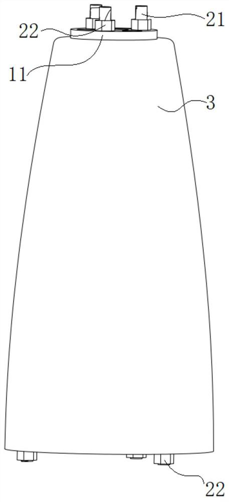
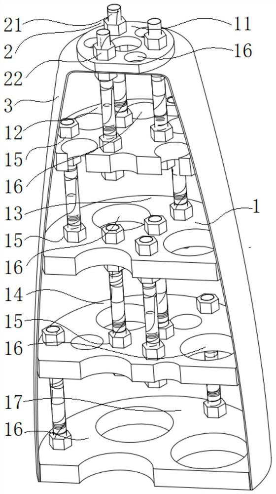
A solid solution treatment and flexible tooling technology, which is applied in heat treatment furnaces, heat treatment equipment, manufacturing tools, etc., can solve the problems of the actual shape of the inner shape and the designed shape, high processing costs, high manufacturing costs, etc., to achieve easy installation and The effect of disassembly, low cost and simple structure

Pending Publication Date: 2021-12-03
海鹰空天材料研究院(苏州)有限责任公司
View PDF0 Cites 0 Cited by
  • Summary
  • Abstract
  • Description
  • Claims
  • Application Information

AI Technical Summary

Problems solved by technology

[0002] Thin-wall aluminum alloy solution treatment is a form of heat treatment with a high risk of deformation, which requires special tooling restrictions, and the heat treatment of long curved busbar parts is particularly difficult
[0003] In the solution treatment of thin-walled aluminum alloy parts on the curved busbar, if the heat treatment tooling is not introduced, the parts will usually have a large amount of deformation, and the parts may not be able to meet the use requirements if the shape is not corrected; while the conventional one-piece non-flexible heat treatment tooling has High requirements on the surface of molded parts, difficult adjustment and high processing costs
[0004] Aluminum alloy rotary parts with a wall thickness of less than 1.5mm are generally formed by spinning or deep drawing. There is an error between the actual shape of the inner shape and the designed shape. The conventional non-flexible inner support heat treatment tooling does not have adjustability and cannot adapt to sheet metal. Differential characteristics of parts and high manufacturing costs

Method used


Image

  • Flexible tool for solution treatment of curved generatrix thin-wall aluminum alloy structural member
  • Flexible tool for solution treatment of curved generatrix thin-wall aluminum alloy structural member

Examples


Embodiment Construction

[0028] The following will clearly and completely describe the technical solutions in the embodiments of the present invention with reference to the accompanying drawings in the embodiments of the present invention. Obviously, the described embodiments are only some, not all, embodiments of the present invention. Based on the embodiments of the present invention, all other embodiments obtained by persons of ordinary skill in the art without making creative efforts belong to the protection scope of the present invention.

[0029] In the description of the present invention, it should be noted that the orientation or positional relationship indicated by the terms "upper", "lower", "bottom", "inner" and "outer" are based on the orientation or positional relationship shown in the drawings , is only for the convenience of describing the present invention and simplifying the description, but does not indicate or imply that the referred device or element must have a specific orientatio...


PUM


Abstract

The invention discloses a flexible tool for solution treatment of curved generatrix thin-wall aluminum alloy structural member. The flexible tool comprises a supporting plate assembly and a fastening assembly, the supporting plate assembly comprises a plurality of supporting plates, the supporting plates comprise the first supporting plate, the second supporting plate, the third supporting plate, the fourth supporting plate and the fifth supporting plate, and a plurality of first through holes and second through holes are uniformly formed in each supporting plate; the fastening assembly comprises a plurality of connecting screw rods and a plurality of nuts; and the first supporting plate and the second supporting plate are connected through the plurality of connecting screw rods, one end of each connecting screw rod penetrates through the corresponding first through hole and is fixed to the first supporting plate through the corresponding nut, and the other end of each connecting screw rod penetrates through the corresponding first through hole and is fixed to the second supporting plate through the corresponding nut. The flexible tool effectively prevents deformation of parts and has a relatively strong adjusting space.

Description

technical field [0001] The invention relates to the field of solid solution treatment of aluminum alloys, in particular to a flexible tooling for solid solution treatment of curved bus bar thin-walled aluminum alloy structural parts. Background technique [0002] Thin-wall aluminum alloy solution treatment is a form of heat treatment with a high risk of deformation, which requires special tooling restrictions, and the heat treatment of long curved busbar parts is particularly difficult. [0003] In the solution treatment of thin-walled aluminum alloy parts on the curved busbar, if the heat treatment tooling is not introduced, the parts will usually have a large amount of deformation, and the parts may not be able to meet the use requirements if the shape is not corrected; while the conventional one-piece non-flexible heat treatment tooling has There are problems such as high requirements on the surface of molded parts, difficult adjustment and high processing cost. [0004]...

Claims


Application Information

Patent Timeline
Patent Type & Authority Applications(China)
IPC IPC(8): C21D9/00C22F1/04
CPCC21D9/0068C21D9/0025C22F1/04
Inventor 许强王东坡赵文龙孙昂张智君李正杰李开春邢朋波
Owner 海鹰空天材料研究院(苏州)有限责任公司
Learn More