Bearing system with oil film pressure detection function

A technology of oil film pressure and function, applied in the direction of rotating bearings, bearings, bearing assembly, etc., can solve the problems of inapplicability and inability to measure oil film pressure, and achieve the effects of convenient layout, reduced friction and simple operation

Pending Publication Date: 2021-12-03
HENAN UNIV OF SCI & TECH
View PDF8 Cites 0 Cited by
  • Summary
  • Abstract
  • Description
  • Claims
  • Application Information

AI Technical Summary

Problems solved by technology

[0006] Although the above can measure the oil film thickness of the bearing, it cannot directly measure the oil film pressure of the bearing during operation. For low-sp...

Method used


Image

  • Bearing system with oil film pressure detection function
  • Bearing system with oil film pressure detection function
  • Bearing system with oil film pressure detection function

Examples


Embodiment 1

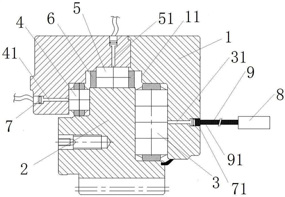
[0043] Such as Figure 1 to Figure 5 As shown, the bearing system with the oil film pressure detection function includes the outer ring 1 and the inner ring 2, the inner ring 2 and the outer ring 1 are rotatably assembled together, and the main thrust roller is installed between the inner ring 2 and the outer ring 1 through the cage 6 3. Auxiliary thrust roller 4 and radial roller 5.

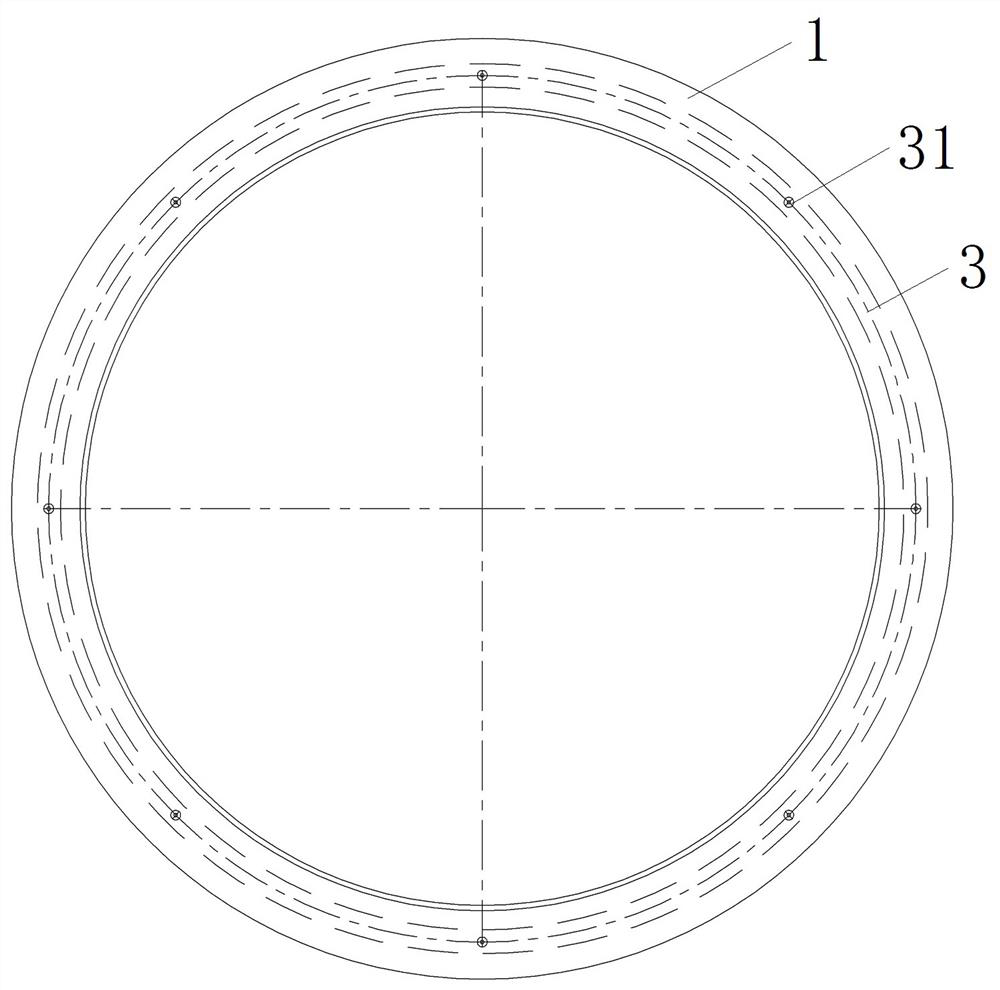
[0044]The outer ring 1 is circular as a whole, the outer side of the outer ring 1 is used for fixed assembly with the corresponding structure of the shield machine, and the inner side of the outer ring 1 is provided with a raceway 11 for the inner ring 2 to rotate and assemble. The outer ring 1 is provided with a main thrust capillary hole 31 , an auxiliary thrust capillary hole 41 and a radial capillary hole 51 , and there are multiple main thrust capillary holes 31 , auxiliary thrust capillary holes 41 and radial capillary holes 51 . The main pushing capillary holes 31 are evenly distributed ...

Embodiment 2

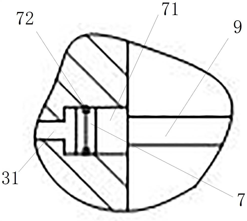
[0053] The difference between this embodiment and Embodiment 1 is that in Embodiment 1, the oil film pressure between the corresponding roller and the outer ring 1 is transmitted to the piston 7 through the lubricating oil in the corresponding capillary hole, and the piston 7 flows to the hydraulic oil pipe 9 The hydraulic oil 91 in the hydraulic oil pipe 9 exerts an outward force to convert the oil film pressure between the corresponding roller and the outer ring 1 into the oil pressure of the hydraulic oil 91 in the hydraulic oil pipe 9 . However, in this embodiment, the hydraulic oil pipe adopts a flexible pipe that can expand and contract. In actual work, when the corresponding roller moves to the position of the corresponding capillary hole, due to the existence of oil film pressure, the distance between the corresponding roller and the outer ring The lubricating oil will enter the corresponding capillary holes, and the lubricating oil in the capillary holes will push the ...

Embodiment 3

[0055] The difference between this embodiment and Embodiment 1 is that in Embodiment 1, a piston cavity 71 is provided at the outer end of each capillary hole for guiding and assembling the piston 7 . In this embodiment, each capillary hole is a straight hole with a constant inner diameter, and the end of the hydraulic oil pipe close to the outer ring is provided with a rigid connecting pipe section. The rigid connecting pipe section extends along the axial direction of the outer ring and is connected to the flange of the outer ring. The guides are fitted in rigidly connected pipe sections.


PUM


Abstract

The invention relates to a bearing system with an oil film pressure detection function. The bearing system comprises an outer ring and an inner ring, both the outer ring and the inner ring are provided with roller paths, and rollers are arranged between the roller paths of the outer ring and the inner ring; capillary holes are formed in the outer ring and/or the inner ring and extend in the inside-outside direction, piston cavities are formed in the outer ends of the capillary holes, pistons are arranged in the piston cavities, the inner ends of the capillary holes communicate with the roller paths, so that when the rollers move to the capillary holes, oil film pressure between the rollers and the outer ring and/or the inner ring is transmitted to the pistons, and oil pressure sensor detection interfaces are arranged at the outer open ends of the piston cavities and used for being connected with the oil pressure sensors so as to detect the oil pressure of the sides, back to the capillary holes, of the pistons. The oil film pressure between the rollers and the outer ring and/or the inner ring is converted into the oil pressure of the sides, back to the capillary holes, of the pistons, the oil pressure measured by the oil pressure sensors is processed so that the oil film pressure between the rollers and the outer ring and/or the inner ring can be obtained, and the oil film pressure in the bearing running process can be accurately measured.

Description

technical field [0001] The invention relates to a bearing system with the function of detecting oil film pressure. Background technique [0002] The bearing mainly includes an inner ring and an outer ring. There are raceways on the inner ring and the outer ring. Rollers are installed between the raceways of the inner ring and the outer ring. The rollers and the raceways are lubricated by lubricating oil, and the lubricating oil film It is an indispensable part in the field of engineering, especially for bearing design, it is an extremely important research content, and for the main bearing of the shield machine, the research on the effect of lubricating oil film on reducing the friction of the main bearing on the surface between solids It is of great significance to improve the service life of the main bearing of the shield machine. [0003] In the prior art, the research on the lubricating oil film of bearings is mainly based on theoretical research, so as to guide the bea...

Claims


Application Information

Patent Timeline
IPC IPC(8): F16C41/00F16C19/50F16C33/58G01L7/00
CPCF16C41/005F16C19/505F16C33/583G01L7/00F16C2233/00
Inventor 苏建新梁志鹏倪元东陈威
Owner HENAN UNIV OF SCI & TECH
Why Eureka
Try Eureka