
Hydrogen leakage monitoring device for hydrogen-oxygen fuel cell

A fuel cell and monitoring device technology, applied to fuel cells, liquid tightness measurement using liquid/vacuum, circuits, etc., can solve problems such as explosion, poor adaptability, and difficult detection, etc., to achieve wide adaptability, Ease of replacement and reduced risk

Pending Publication Date: 2021-12-03
ZHENGZHOU UNIV
View PDF16 Cites 0 Cited by
  • Summary
  • Abstract
  • Description
  • Claims
  • Application Information

AI Technical Summary

Problems solved by technology

[0003] Most of the existing hydrogen leakage monitoring devices use a straight tube to inhale the hydrogen gas near the battery to react the hydrogen gas, so as to judge whether the battery leaks hydrogen gas, but the internal hydrogen gas cannot be discharged during use, which will affect the detection results of each fuel cell during continuous detection. , and the end of the straight tube cannot isolate the external air, it is easy to mix high-purity hydrogen with air to cause an explosion, and the inhalation of hydrogen in the air makes it impossible to find the specific location of the leak. At the same time, when the leak is at the corner of the battery It is even more difficult to detect when the hydrogen gas reacts inside the detection device, and it is difficult to completely flow out the water droplets produced after the hydrogen gas reacts inside the detection device, which will speed up the oxidation speed of other parts in the device, and the adaptability is not good enough

Method used


Image

  • Hydrogen leakage monitoring device for hydrogen-oxygen fuel cell
  • Hydrogen leakage monitoring device for hydrogen-oxygen fuel cell
  • Hydrogen leakage monitoring device for hydrogen-oxygen fuel cell

Examples


Embodiment Construction

[0024] The following will clearly and completely describe the technical solutions in the embodiments of the present invention with reference to the accompanying drawings in the embodiments of the present invention. Obviously, the described embodiments are only some, not all, embodiments of the present invention.

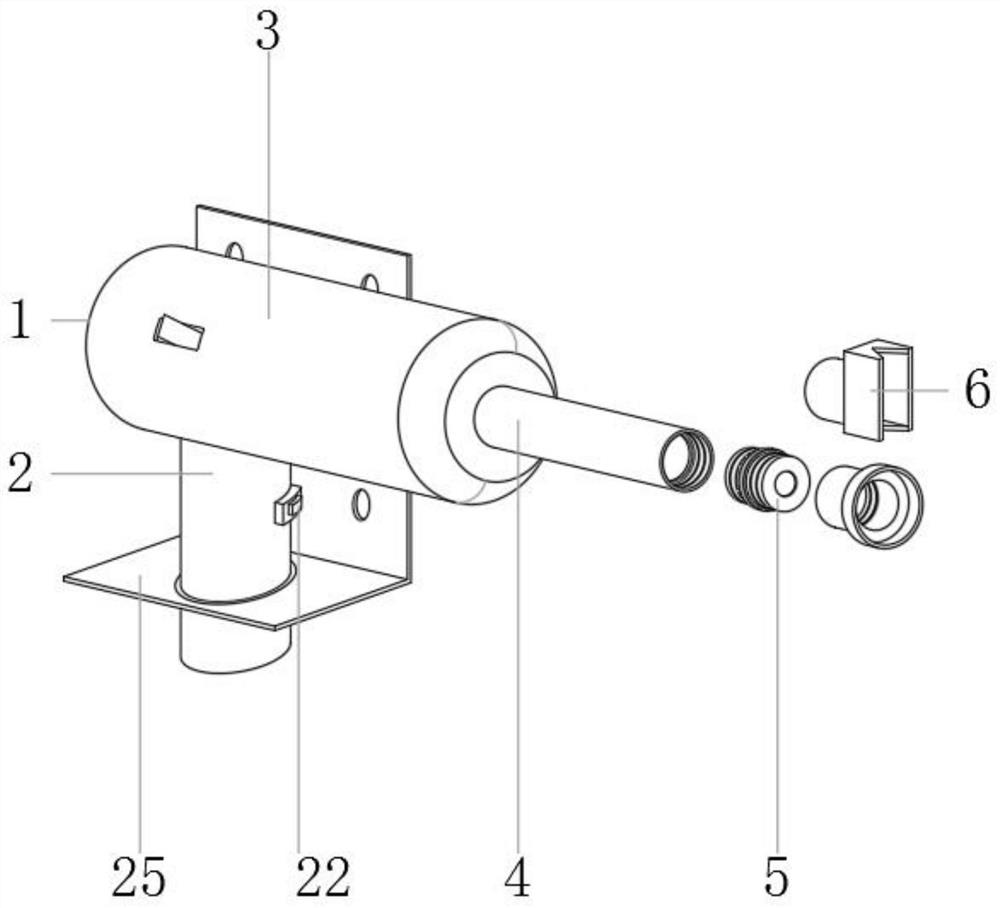
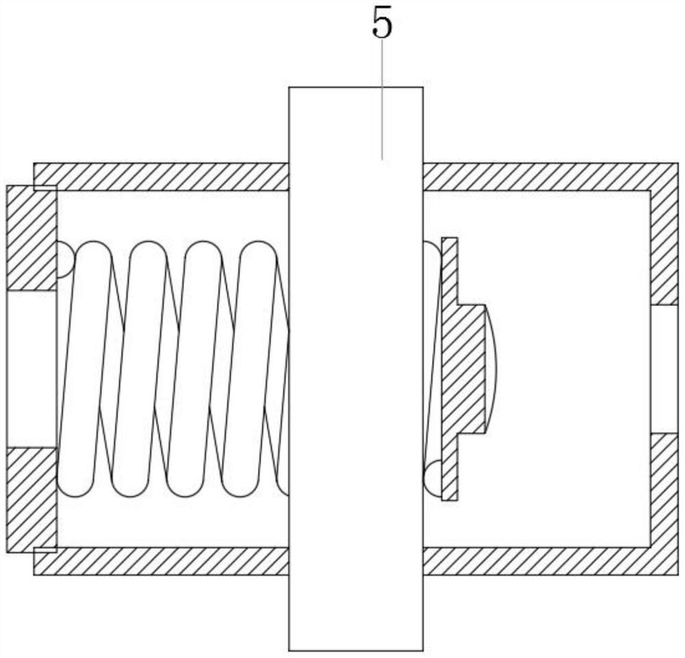
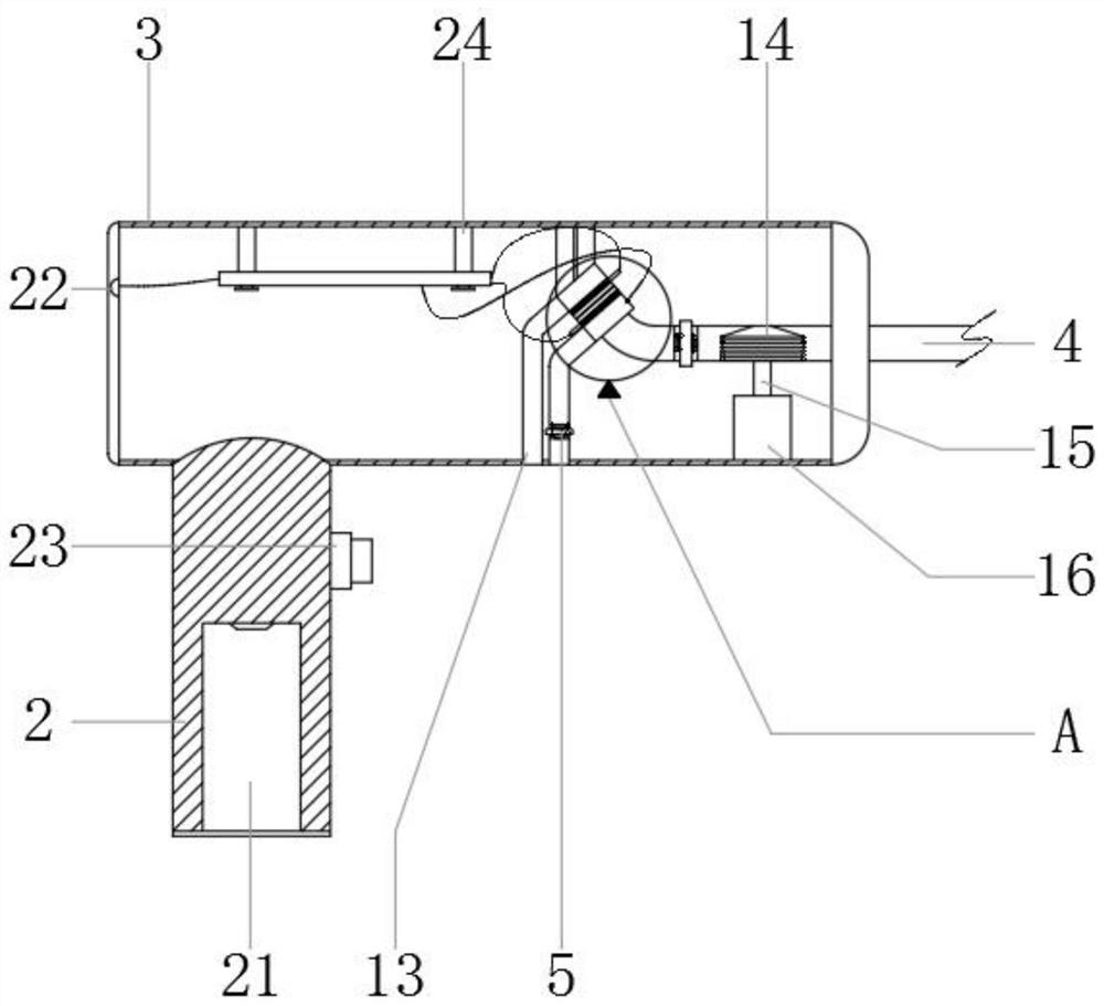
[0025] refer to Figure 1-6 , a hydrogen leakage monitoring device for hydrogen-oxygen fuel cells, including a housing 1, the housing 1 includes a handle 2 and a cylindrical shell 3, the handle 2 is convenient for the inspector to hold the device for detection, and the inner surface of the cylindrical shell 3 is inserted Connected with a straight pipe 4, the straight pipe 4 is the channel through which the hydrogen gas leaked from the detected battery is sucked into the reaction cylinder 8. The inner surface of the straight pipe 4 is threaded with a one-way valve 5, and the initial state of the inner spring of the one-way valve 5 is a compressed state , so that the t...


PUM


Abstract

The invention discloses a hydrogen leakage monitoring device for a hydrogen-oxygen fuel cell. The hydrogen leakage monitoring device comprises a shell, the shell comprises a grip and a barrel shell, a straight pipe is inserted into the inner side face of the barrel shell, a one-way valve is installed on the inner side face of the straight pipe in a threaded mode, and an abutting head is installed at the end, away from the straight pipe, of the outer surface of the one-way valve in a threaded mode; a reaction cylinder is arranged at the outlet end, away from the straight pipe, of a bent pipe, and a diaphragm head is slidably mounted on the side, close to the bent pipe, of the inner side face of the straight pipe. According to the invention, the abutting head is convenient to replace, the device can adapt to the situation that leakage holes are distributed in different positions of the battery, and when the abutting head is in contact with the detected battery, hydrogen in external air can be prevented from entering the straight pipe to influence the judgment of detection personnel on the positions of the leakage holes; water drops generated after the reaction are difficult to remain in the device, so that the oxidation speed of other parts is increased, and the situation that the detection result of each fuel cell is affected due to the fact that hydrogen in the device is not discharged during continuous detection can be avoided.

Description

technical field [0001] The invention relates to the technical field of battery detection, in particular to a hydrogen leakage monitoring device for a hydrogen-oxygen fuel cell. Background technique [0002] Fuel cells are promising new power sources, generally using hydrogen, carbon, methanol, borohydride, coal gas or natural gas as fuel, as the negative electrode, and oxygen in the air as the positive electrode. The main difference from general batteries is that the active substances of general batteries are pre-placed inside the battery, so the battery capacity depends on the amount of active substances stored; while the active substances (fuel and oxidant) of fuel cells are continuously flowing while reacting. Ground input, therefore, this type of battery is actually just an energy conversion device. This type of battery has the advantages of high conversion efficiency, large capacity, high specific energy, wide power range, and no charging, but due to high cost and comp...

Claims


Application Information

Patent Timeline
Patent Type & Authority Applications(China)
IPC IPC(8): G01M3/16H01M8/04664
CPCG01M3/16H01M8/04664Y02E60/50
Inventor 陈本海秦东晨
Owner ZHENGZHOU UNIV
Learn More