
A power supply overheat protection circuit and calibration method thereof

A technology of overheat protection circuit and calibration method, which is applied in the direction of emergency protection circuit devices, circuits, circuit devices, etc., and can solve the problem that the temperature fluctuation of high-precision power supply cannot be satisfied, the effect of circuit overheat protection is affected, and the heat cannot be timely Dispersion and other problems, to achieve the effect of improving effective protection, low delay, and improving work reliability

Active Publication Date: 2022-05-03
深圳市响河测控技术有限公司
View PDF6 Cites 0 Cited by
  • Summary
  • Abstract
  • Description
  • Claims
  • Application Information

AI Technical Summary

Problems solved by technology

The speed of signal transmission and feedback in this method is too slow to meet the temperature fluctuation requirements of high-precision power supplies
At the same time, since the power management modules are packaged finished products, different packages have a great impact on heat dissipation. If the package is poor, the heat generated by the power management module chip cannot be dissipated in time. At this time, the temperature detected externally is no longer The actual temperature of the power module is lower, and the external temperature is not high, but the power chip may have been burned out, which affects the effect of the circuit overheating protection

Method used


Image

  • A power supply overheat protection circuit and calibration method thereof
  • A power supply overheat protection circuit and calibration method thereof
  • A power supply overheat protection circuit and calibration method thereof

Examples


Embodiment Construction

[0031] Embodiments of the present invention are described in detail below, examples of which are shown in the drawings, wherein the same or similar reference numerals designate the same or similar elements or elements having the same or similar functions throughout. The embodiments described below by referring to the figures are exemplary only for explaining the present invention and should not be construed as limiting the present invention.

[0032] It should be noted that when an element is referred to as being “fixed” to another element, it can be directly on the other element or there can also be an intervening element. When an element is referred to as being "connected to" another element, it can be directly connected to the other element or intervening elements may also be present. In contrast, when an element is referred to as being "directly on" another element, there are no intervening elements present. The terms "vertical," "horizontal," "left," "right," and similar...


PUM


Abstract

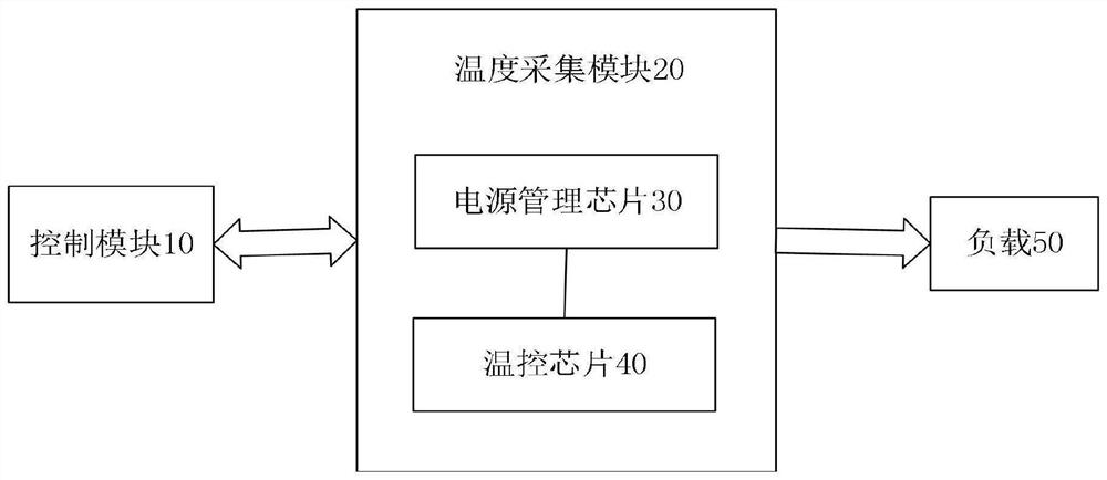
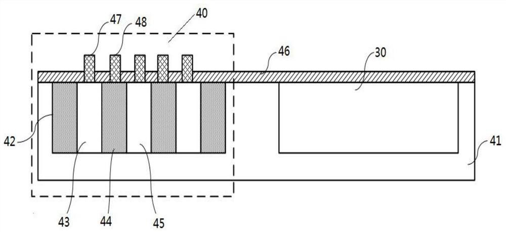
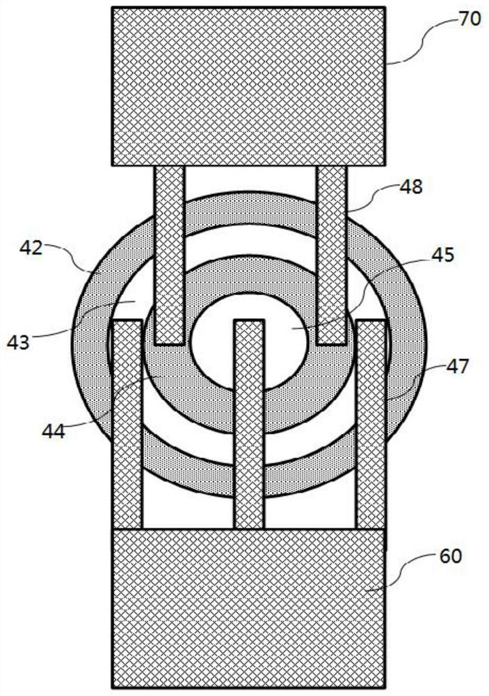
The invention discloses a power supply overheating protection circuit including a control module and a temperature acquisition module, the temperature acquisition module includes a power management chip, and a temperature control chip packaged with the power management chip, the temperature control chip includes a substrate, and a first interval formed in the substrate An implanted region, a second implanted region located between the first implanted regions, a third implanted region located between the second implanted regions, a fourth implanted region located between the third implanted regions, a medium located on the upper surface of the substrate layer, the first electrode and the second electrode that penetrate the dielectric layer respectively correspond to the second injection area and the third injection area, and the power management chip is formed in the substrate and connected to the dielectric layer. When the temperature of the temperature control chip rises, the control The module detects a change in the voltage drop between the first electrode and the second electrode, and controls the power management chip to shut down if the temperature exceeds the preset temperature for safe operation of the power management chip. Improve the effective protection of the overheating circuit of the power supply, and also meet the temperature fluctuation requirements of the high-precision power supply.

Description

technical field [0001] The invention relates to the technical field of power supply management, in particular to a power supply overheating protection circuit and a calibration method thereof. Background technique [0002] With the development of electronic technology, the power of the system is getting higher and higher, and the heat will also become more and more serious. Excessive heat will cause damage to the power supply, resulting in system downtime or other dangers. The current power supply overheating protection mainly detects the temperature of the power supply system through thermal elements or other temperatures, and then converts it into an electrical signal to finally determine the on-off of the power supply. The speed of signal transmission and feedback in this method is too slow to meet the temperature fluctuation requirements of high-precision power supplies. At the same time, since the power management modules are packaged finished products, different packa...

Claims


Application Information

Patent Timeline
Patent Type & Authority Patents(China)
IPC IPC(8): H01L29/06H02H5/04G01K13/00
CPCH01L29/0642H01L29/063H02H5/044G01K13/00
Inventor 刘金鑫黄欣陈生保殷家刚罗换名
Owner 深圳市响河测控技术有限公司
Learn More