Back contact solar cell, assembly and system

A solar cell and back contact technology, which is applied in the field of solar cells, can solve the problems of increasing production costs, heavy workload of sub-cells in series, and affecting the production efficiency of full back contact solar cells, so as to simplify the interconnection process and save electrode paste , the effect of improving the preparation efficiency

Active Publication Date: 2021-12-03
TAIZHOU ZHONGLAI PHOTOELECTRIC TECH CO LTD
View PDF12 Cites 0 Cited by
  • Summary
  • Abstract
  • Description
  • Claims
  • Application Information

AI Technical Summary

Problems solved by technology

However, when preparing metal electrodes, it is necessary to cut off the excess wires at the edge of the battery, that is, one side needs to cut off the wires of the N region at intervals, and the other side needs to cut off the wires of the P region at intervals. However, the electrodes of the N region The metal wires and the metal wires of the P-region electrodes are arranged alternately, and the number of metal wires is large. Therefore, the cutting process of the metal wires is extremely cumbersome, which affects the preparation efficiency of the full back contact solar cell.
Moreover, when preparing a battery assembly, it is usually necessary to cut the full-back contact solar cell to form a plurality of sub-cells, and then rotate one of the two adjacent sub-cells, and then use bus bars to separate the N-region of a sub-cell. The wire of the electrode is welded to the bus bar, and then the bus bar is welded to the wire of the P-region electrode of another sub-battery after rotation, so as to realize the series connection between the sub-batteries to obtain the battery assembly; , the number of metal wires is large, so the welding process of the bus bar and the metal wire is extremely cumbersome, resulting in a huge workload for the series connection of the sub-batteries, and the need to rotate the sub-battery and input the consumable bus bar, which leads to low production efficiency of the battery assembly , and greatly increased its production cost

Method used


Image

  • Back contact solar cell, assembly and system
  • Back contact solar cell, assembly and system

Examples


Embodiment 1

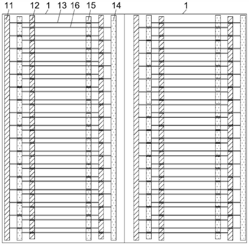
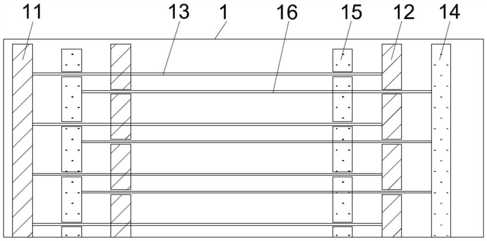
[0027] In the back contact solar cell of this embodiment, p+ emitter regions and n+ base regions are alternately arranged on the back surface. Wherein, the back contact solar cell includes at least two sub-cells 1 arranged in sequence, and the back surface of each sub-cell 1 is provided with a back electrode; the back electrode includes alternately arranged emitter electrodes and base electrodes, and the emitter electrodes are arranged on the p+ emitter. The back surface of the pole region, so that the emitter electrode can be connected to the p+ emitter region to realize current transmission, and the base electrode is arranged on the back surface of the n+ base region, so that the base electrode can be connected to the n+ base region to realize current transmission, The above configurations of the emitter electrode, p+ emitter region, base electrode and n+ base region are all conventional configurations of back-contact solar cells, and will not be repeated here. Preferably, b...


PUM

PropertyMeasurementUnit
electrical resistivityaaaaaaaaaa

Abstract

A back contact solar cell comprises at least two sub-cells, back electrodes are arranged on the back surfaces of the sub-cells, and the back electrodes comprise emission electrodes and base electrodes which are alternately arranged; each emitting electrode is provided with a first emitting electrode which is positioned on the same side of each sub-battery and is arranged in a whole section, each base electrode is provided with a first base electrode which is positioned on the other side of each sub-battery and is arranged in a whole section, and a segmented second emitting electrode and a segmented second base electrode are arranged between the first emitting electrode and the first base electrode of each sub-battery; in each sub-cell, the first emission electrode and the second emission electrode are connected with a first wire which penetrates through the second base electrode and is separated in a segmented manner, and the first base electrode and the second base electrode are connected with a second wire which penetrates through the second emission electrode and is separated in a segmented manner; the segmentation positions of the second emission electrodes and the second base electrodes of two adjacent sub-cells are staggered from each other; and the back electrodes can improve the cell preparation efficiency, can achieve the effect of reducing series resistance of a half cell without rotation after slicing, and simplifies the cell assembly preparation process.

Description

technical field [0001] The invention relates to the technical field of solar cells, in particular to a back contact solar cell, component and system. Background technique [0002] A solar cell is a semiconductor device that converts light energy into electrical energy. At present, the emitter and base of a conventional solar cell are located on the front and back of the cell, respectively. Both the emitter and the base of the back contact solar cell are located on the back of the cell, and the front of the cell (that is, the light-receiving surface) is not blocked by any metal electrodes, which can effectively increase the short-circuit current of the cell and significantly improve the conversion efficiency of the cell. [0003] The metallization process of back-contact solar cells has always been a difficult point in the industrial mass production process. In the previous preparation process of back-contact solar cells, the metallization process was mostly realized by the e...

Claims


Application Information

Patent Timeline
Patent Type & Authority Applications(China)
IPC IPC(8): H01L31/0224
CPCH01L31/022441Y02E10/50
Inventor 沈承焕陈程季根华赵影文包杰陈嘉林建伟
Owner TAIZHOU ZHONGLAI PHOTOELECTRIC TECH CO LTD
Why Eureka
Try Eureka