Dust removal device for electrical automation equipment

A technology of electrical automation and dust removal device, applied in the direction of cleaning methods, cleaning methods and utensils, chemical instruments and methods using gas flow, etc., can solve problems such as single blowing, secondary pollution, electrical short circuit, etc. The effect of preventing secondary pollution and simple operation

Active Publication Date: 2021-12-07
HENAN POLYTECHNIC INST
View PDF10 Cites 1 Cited by
  • Summary
  • Abstract
  • Description
  • Claims
  • Application Information

AI Technical Summary

Problems solved by technology

[0004] After the electrical automation equipment in the prior art is used for a long time, dust is easy to accumulate in the internal electrical components, and the dust accumulated in the electronic board will not only affect the heat dissipation of the equipment, but also cause serious situations such as electrical short circuits. , causing great harm to the safe operation of electrical components. Existing dust removal devices for electrical automation equipment can only blow a single blow to the surface of the equipment to blow the dust away from the surface of the electrical components. When the electrical components inside the equipment are relatively For a long time, after the dust is blown away, it will fall on the surface of other electrical components, which is easy to cause secondary pollution, and it is difficult to clean up the raised dust in time. In view of this, we propose a dust removal device for electrical automation equipment

Method used


Image

  • Dust removal device for electrical automation equipment
  • Dust removal device for electrical automation equipment
  • Dust removal device for electrical automation equipment

Examples


Embodiment Construction

[0033] The following description serves to disclose the present invention to enable those skilled in the art to carry out the present invention. The preferred embodiments described below are only examples, and those skilled in the art can devise other obvious variations.

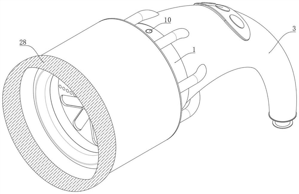
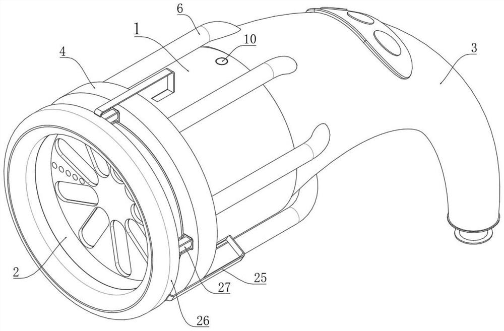
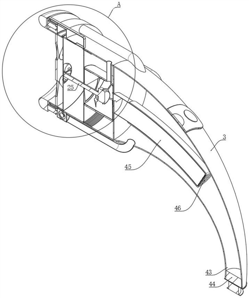
[0034] like Figure 1 to Figure 10 The shown dust removal device for electrical automation equipment includes a cylinder body 1, an opening 2 is opened at one end of the cylinder body 1, and an annular elastic breathable cover 28 is fixedly connected to the surface of the cylinder body 1 close to the opening 2, and the cylinder body 1 The other end of the cylinder is fixed with a collection bucket 3, and a dust collection ring 4 is fixed on the side wall of the cylinder 1 at the edge of the opening 2. A plurality of dust inlet holes 5 are opened between the dust collection ring 4 and the cylinder 1, and the dust collection A plurality of conveying pipes 6 are fixedly connected between the ring 4 and the col...


PUM


Abstract

The invention relates to the technical field of electrical automation equipment, in particular to a dust removal device for the electrical automation equipment. The dust removal device comprises a cylinder body, wherein an opening is formed in one end of the cylinder body; the other end of the cylinder body is fixedly provided with a collecting barrel; the side wall of the cylinder body is fixedly sleeved with a dust collecting ring at the edge of the opening; a plurality of dust inlet holes are formed between the dust collecting ring and the cylinder body; a plurality of conveying pipes are fixedly arranged between the dust collecting ring and the collecting barrel in a communicating manner; a dust discharging mechanism is arranged at the tail end of the collecting barrel; an equipment cylinder is fixed in the cylinder body; a gas flow leading mechanism is arranged in the equipment cylinder; a fan-shaped gas discharging opening and a fan-shaped gas inlet are separately formed in the two ends of the equipment cylinder; the gas discharging opening communicates with the interior of the cylinder body; the gas inlet communicates with the interior of the collecting barrel; and a gas inlet pipe and a gas outlet pipe are fixed to the inner wall of the equipment cylinder in a communicating manner. According to the dust removal device, dust on an electrical component is blown so as to be loosened, and then the gas flow direction can be changed in time. The raised dust can be conveniently cleared away in time, and secondary pollution is prevented.

Description

technical field [0001] The invention relates to the field of electrical automation equipment, in particular to a dust removal device for electrical automation equipment. Background technique [0002] Automation refers to the process of automatic detection, information processing, analysis and judgment, manipulation and control of machines, equipment, systems or processes (production, management processes) without the direct participation of people or fewer people, according to people's requirements, to achieve the expected goals. process. [0003] Some invention patents related to dust removal devices have been disclosed in the prior art. The Chinese patent application number 202010197235.X discloses a circuit board cleaning and dust removal equipment, which includes a connecting block, and a rotating wheel is rotatably connected inside the connecting block. A driving motor is fixed inside the rotating wheel, and the lower end of the driving motor is connected with an air i...

Claims


Application Information

Patent Timeline
Patent Type & Authority Applications(China)
IPC IPC(8): B08B5/02B08B5/04
CPCB08B5/02B08B5/04
Inventor 袁铸申一歌王记昌靳果袁苏楠华显立孟庆辉党淼石新龙陈贞来
Owner HENAN POLYTECHNIC INST
Why Eureka
Try Eureka