A disc brake device for kinetic energy conversion of new energy vehicles

A new energy vehicle, kinetic energy conversion technology, applied in the direction of control device, auxiliary drive device, brake, etc., can solve the problem of affecting the service life of linear motor, wear of convex teeth and cogging, aggravating the loss of components, etc., so as to shorten the braking time. , reduce wear time, improve the effect of braking capacity

Active Publication Date: 2022-02-15
杭州智科精密机械有限公司
View PDF11 Cites 0 Cited by
  • Summary
  • Abstract
  • Description
  • Claims
  • Application Information

AI Technical Summary

Problems solved by technology

[0005] However, in the actual use of the kinetic energy recovery device of this application, we found that when the state switching at both ends of the torsion elastic member relies on the telescopic movement of the linear motor, and uses the engagement of the convex teeth and the tooth grooves to achieve rotational docking, although It can realize docking and switching, but the wear and tear on the convex teeth and the tooth grooves is extremely serious during the whole process, and because the real-time positions and states of the corresponding convex teeth and tooth grooves are not fixed, it is easy to cause rigidity when the convex teeth and tooth grooves are docked. Contact collision, that is, the convex teeth are not aligned with the tooth grooves, which not only further aggravates the loss of the component, but also makes the linear motor continue to work and elongate. It cannot be stretched, and at the same time seriously affects the service life of its linear motor. Therefore, we propose a disc brake device for kinetic energy conversion of new energy vehicles

Method used


Image

  • A disc brake device for kinetic energy conversion of new energy vehicles
  • A disc brake device for kinetic energy conversion of new energy vehicles
  • A disc brake device for kinetic energy conversion of new energy vehicles

Examples


Embodiment Construction

[0037] The following will clearly and completely describe the technical solutions in the embodiments of the present invention with reference to the accompanying drawings in the embodiments of the present invention. Obviously, the described embodiments are only some, not all, embodiments of the present invention. Based on the embodiments of the present invention, all other embodiments obtained by persons of ordinary skill in the art without making creative efforts belong to the protection scope of the present invention.

[0038] The invention provides a technical solution:

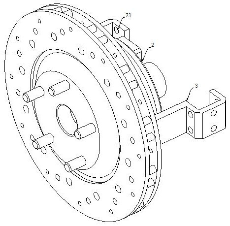
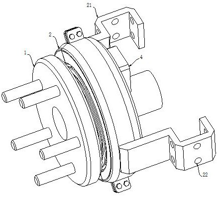
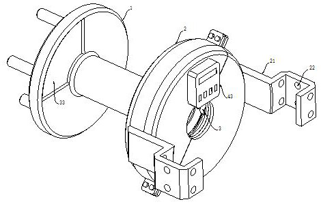
[0039] refer to Figure 1-2 As shown, a disc brake device for kinetic energy conversion of new energy vehicles includes a disc 1 located at the end of the drive shaft of the vehicle hub and used for brake disc installation, and the disc 1 is coaxial with the brake disc;

[0040] It also includes an installation collar 2, and both sides of the installation collar 2 are provided with installation brackets 21...


PUM


Abstract

The invention discloses a disc brake device for kinetic energy conversion of a new energy vehicle, which comprises a disc located at the end of the drive shaft of the hub of the vehicle and used for installing a brake disc. The disc is coaxial with the brake disc. It includes an installation collar, and both sides of the installation collar are provided with installation brackets, and the two installation brackets are provided with through installation holes, and are installed on the automobile suspension by bolts, and wrapped around the drive shaft The outer side rotates coaxially with the wheel disc. This new energy vehicle kinetic energy conversion braking device is different from the existing technology. During the braking process of the new energy vehicle, it can be synchronously touched by the electromagnetic docking parts, and then drive the elastic energy storage mechanism in the vehicle. At the same time of braking, the kinetic energy of the car is converted into elastic potential energy, and in the process of energy storage, its continuously increasing elastic potential energy can also provide reverse elastic resistance for the car wheel to assist driving braking, thereby increasing new energy car braking effect.

Description

technical field [0001] The invention relates to the technical field of kinetic energy conversion braking of new energy vehicles, in particular to a disc brake device for kinetic energy conversion of new energy vehicles. Background technique [0002] Most of the existing new energy vehicles use the traditional vehicle braking system to dissipate the kinetic energy of the vehicle into the air in the form of heat through the wheel brakes and brake discs or brake drums; Kinetic energy is recovered into the power battery. [0003] However, the traditional method of dissipating the kinetic energy of the vehicle into the air in the form of heat energy will cause the brakes to heat up rapidly, causing thermal decay, resulting in an increase in the braking distance, and even causing the brakes to fail, and greatly shortening the service life of the brake shoes. In addition, although some new energy vehicles are also equipped with a braking energy recovery system, that is, a system t...

Claims


Application Information

Patent Timeline
Patent Type & Authority Patents(China)
IPC IPC(8): B60T1/10B60K25/00
CPCB60T1/10B60K25/00
Inventor 洪伟纯
Owner 杭州智科精密机械有限公司
Why Eureka
Try Eureka