
Horizontal test device and method for Seebeck coefficient and conductivity of thermoelectric material

A Seebeck coefficient and testing equipment technology, which is applied in the direction of material thermal development, measuring resistance/reactance/impedance, measuring devices, etc., can solve the problems of prone to error, failure to simultaneously test the conductivity of thermoelectric materials, and inconvenient operation , to achieve the effect of simple test

Pending Publication Date: 2021-12-07
XIAMEN INST OF RARE EARTH MATERIALS
View PDF0 Cites 1 Cited by
  • Summary
  • Abstract
  • Description
  • Claims
  • Application Information

AI Technical Summary

Problems solved by technology

The existing Seebeck coefficient testing equipment is usually only for bulk or thin film thermoelectric materials
Moreover, the sample stage of the bulk Seebeck coefficient test instrument is usually vertical, which is inconvenient to operate when placing the sample
In addition, the existing thin film testing equipment adopts non-contact laser irradiation heating method. Since the laser itself will have a certain impact on the physical properties of the material, it is easy to produce errors when testing materials that are sensitive to light or have different reflectivities.
In addition, the existing Seebeck coefficient testing equipment can usually only test the Seebeck coefficient in the temperature range above normal temperature
At the same time, electrical conductivity is another important physical parameter of thermoelectric materials, but the existing technology fails to simultaneously test the electrical conductivity of thermoelectric materials at high temperature and low temperature

Method used


Image

  • Horizontal test device and method for Seebeck coefficient and conductivity of thermoelectric material
  • Horizontal test device and method for Seebeck coefficient and conductivity of thermoelectric material
  • Horizontal test device and method for Seebeck coefficient and conductivity of thermoelectric material

Examples


Embodiment 1

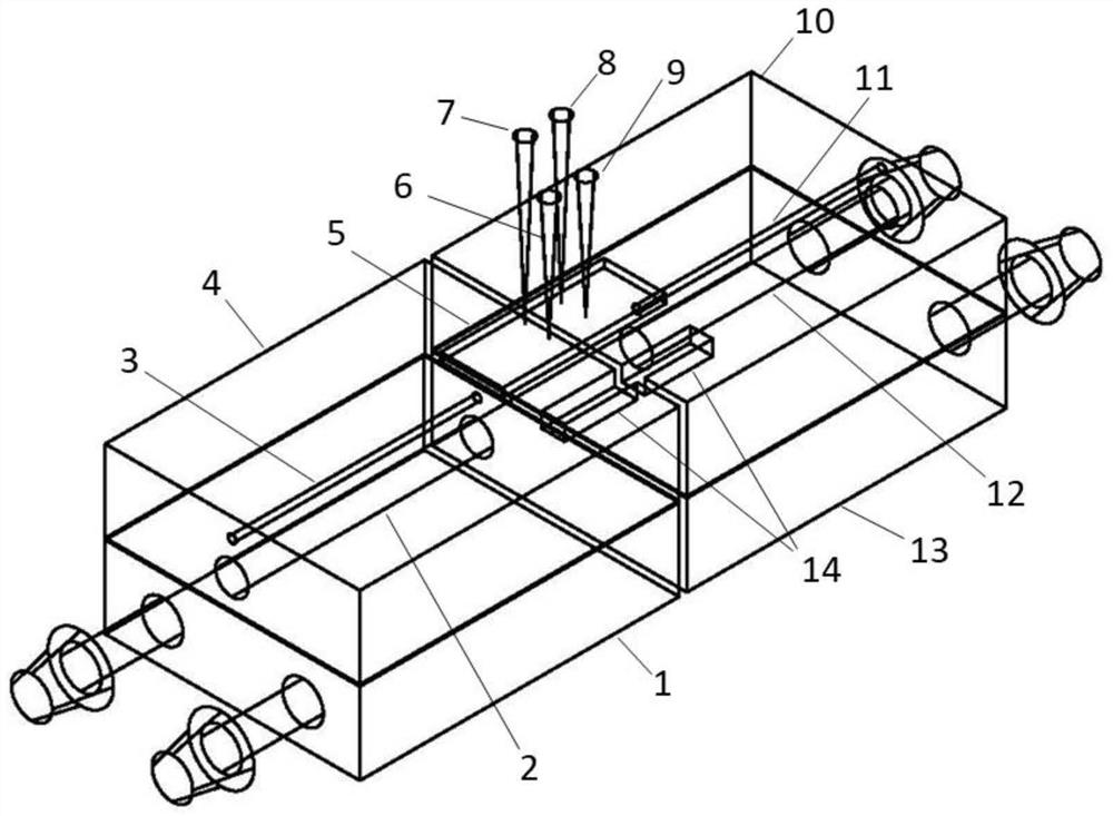
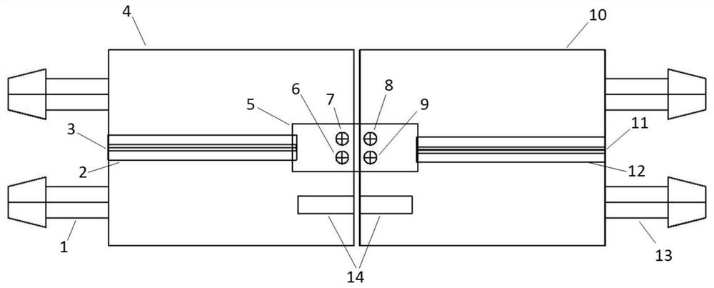
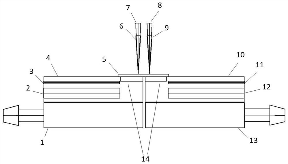
[0104] like Figure 1-4 The horizontal test equipment for the Seebeck coefficient of thermoelectric materials is shown, which is suitable for testing thermoelectric thin film materials. The test equipment includes a first test unit and a second test unit connected in parallel.

[0105] The first test unit includes a first cooling system 1, a first heating rod 2, a first temperature sensor 3, a first heating block 4, a first temperature measuring probe 6, a first voltage testing probe 7, and a second voltage testing probe Probe 8.

[0106] The second testing unit includes a second cooling system 13 , a second heating rod 12 , a second temperature sensor 11 , a second heating block 10 , a second temperature measuring probe 9 , and a second voltage testing probe 8 . The first heating block 4 and the second heating block 10 are horizontally placed side by side, and the first heating block 4 and the second heating block 10 jointly carry the film sample 5 to be tested, that is, th...

Embodiment 2

[0115] like Figure 9-11 As shown in the testing equipment for simultaneously testing Seebeck coefficient and electrical conductivity, in addition to the components of the equipment in Embodiment 1, the first testing unit also includes the conductive needle 7'a of the first current testing probe, and the second testing unit It also includes a conductive needle body 8'a of the second current test probe.

[0116] Figure 9 A three-dimensional schematic diagram of the four-probe method for testing the conductivity of thin film materials, Figure 10 Three-dimensional schematic diagram for testing the conductivity of bulk materials by the four-probe method. Figure 9 Among them, the conductive needle body 7'a of the first current test probe, the first voltage test probe 7, the second voltage test probe 8, and the conductive needle body 8'a of the second current test probe are sequentially arranged in a line Set on a straight line passing through the geometric center of the sampl...

Embodiment 3

[0121] Example 3: Polycrystalline N-type Bi 2 Te 3 Thin film Seebeck coefficient test

[0122] Using the testing equipment that embodiment 1 provides, to polycrystalline N-type Bi 2 Te 3 The Seebeck coefficient of the film is tested:

[0123] A1) Polycrystalline N-type Bi 2 Te 3 The film is placed on the first heating block and the second heating block, and the distance between the first heating block and the second heating block is adjusted according to the size of the film sample to ensure that the sample is completely placed on the surface of the heating block;

[0124] A2) The first temperature measurement probe and the first voltage test probe are in contact with one end of the film sample, and the distance between the probes is less than 1mm; the second temperature measurement probe and the second voltage test probe are connected to the other end of the film sample One end is in contact and the distance between the probes is less than 1mm.

[0125] A3) Before the ...


PUM


Abstract

The invention discloses a horizontal test device and method for Seebeck coefficient and conductivity of a thermoelectric material. The equipment provided by the invention is provided with two cooling systems, so that the Seebeck coefficient of a material when the temperature is lower than room temperature can be tested, and meanwhile, after the previous test is completed, the heater can be quickly recovered to a relatively low temperature, so that the test of a next sample can be quickly started, the sample test is simpler and more convenient, and the efficiency of testing a plurality of temperatures of a plurality of samples is improved. According to the invention, a contact heating mode is adopted, and a double-heating table mode is adopted, so that any temperature difference can be accurately and quickly provided for a test sample. The distance between the two heating blocks can be adjusted and controlled, the surface is provided with the groove, and a block sample can be placed in the groove, so that the purpose of testing the block sample and a film sample can be simultaneously met.

Description

technical field [0001] The invention belongs to the field of testing thermoelectric properties of materials, and in particular relates to a horizontal testing device and method for Seebeck coefficient and electrical conductivity of thermoelectric materials. Background technique [0002] A thermoelectric material is a material that can convert a temperature difference into an electric potential difference and vice versa. Its working principle is based on the thermoelectric effect of the material: when a temperature difference is established at both ends of the material, the carriers in the material will diffuse from the heat source (high temperature end) to the heat well (low temperature end) due to heat conduction, thereby generating a potential difference , and convert heat energy into electrical energy, which is the principle of thermoelectric power generation; on the contrary, when a voltage is applied to both ends of a thermoelectric material, one end of the material wil...

Claims


Application Information

Patent Timeline
IPC IPC(8): G01N25/20G01R27/08
CPCG01N25/20G01R27/08
Inventor 吴挺俊高鹏
Owner XIAMEN INST OF RARE EARTH MATERIALS
Learn More