

Dynamic bias circuit applied to LDO (Low Dropout Regulator) and LDO using dynamic bias circuit
A technology of bias circuit and bias current applied to LDO. It can solve the problems of low static power consumption and increase the static power consumption of the circuit, and achieve the effects of low power consumption design, reduced power consumption, low power consumption and fast transient response
- Summary
- Abstract
- Description
- Claims
- Application Information
AI Technical Summary
Problems solved by technology
Method used
Image

Examples
Embodiment 1
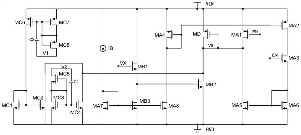
[0045] refer to figure 1 , this embodiment discloses a dynamic bias circuit applied to LDO, including a constant bias current generation module, an adaptive steady-state bias current generation module, an adaptive transient bias current generation module and a bias voltage generation module;
[0046] The bias voltage generating module includes a PMOS transistor M D , PMOS tube M D The source is connected to the power supply voltage VIN, and the gate and drain are connected as the output terminal V B , the drain is also connected to the PMOS tube M A1 The drain and NMOS transistor M B2 the drain.
[0047] The bias voltage generation module can convert different types of input bias currents into bias voltages from the output terminal V B output.
[0048] The constant bias current generating module includes a PMOS transistor M A1 , M A2 , M A3 , M A4 , NMOS tube M A5 , M A6 , M A7 , M A8 and current source I B .
[0049] Current source I B One end of the power su...
Embodiment 2
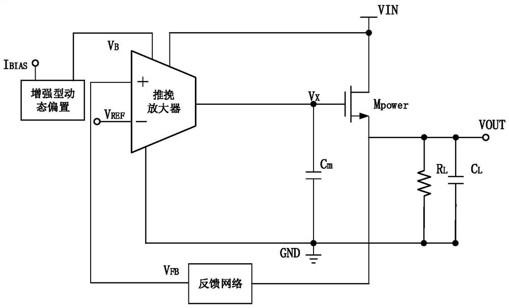
[0063] refer to image 3 , this embodiment discloses a capacitor LDO applying the dynamic bias circuit of Embodiment 1, including a dynamic bias circuit, a push-pull amplifier, a power adjustment tube M Power , compensation capacitor C m , capacitance C L and resistor R L , the dynamic bias circuit is an enhanced dynamic bias circuit, and the input terminal of the enhanced dynamic bias circuit is connected to the reference current I BIAS flow, the output is connected to the V of the push-pull amplifier B terminal, the non-inverting input terminal of the push-pull amplifier is connected to the output terminal V through the feedback network out , the inverting input terminal is connected to the reference voltage V ref , the output terminal is connected to the power adjustment tube M Power The gate, the power adjustment tube M Power The drain of the input terminal V IN , the source is connected to the output terminal V out , compensation capacitor C m One end of the pus...
PUM
 Abstract
Description
Claims
Application Information