Transmitter

A technology of air conditioning device and operation control, which is applied to circuit devices, selection devices, telemetry/remote selection devices, etc., and can solve problems such as time required

Inactive Publication Date: 2004-02-04
DAIKIN IND LTD
View PDF1 Cites 0 Cited by
  • Summary
  • Abstract
  • Description
  • Claims
  • Application Information

AI Technical Summary

Problems solved by technology

In other words, once the outdoor unit connected to the power superimposition circuit is determined, the automatic setting operation must be performed again when

Method used


Image

  • Transmitter
  • Transmitter
  • Transmitter

Examples


Embodiment Construction

[0093]

[0094] Hereinafter, Embodiment 1 of the present invention will be described in detail with reference to the drawings.

[0095] -Overall composition-

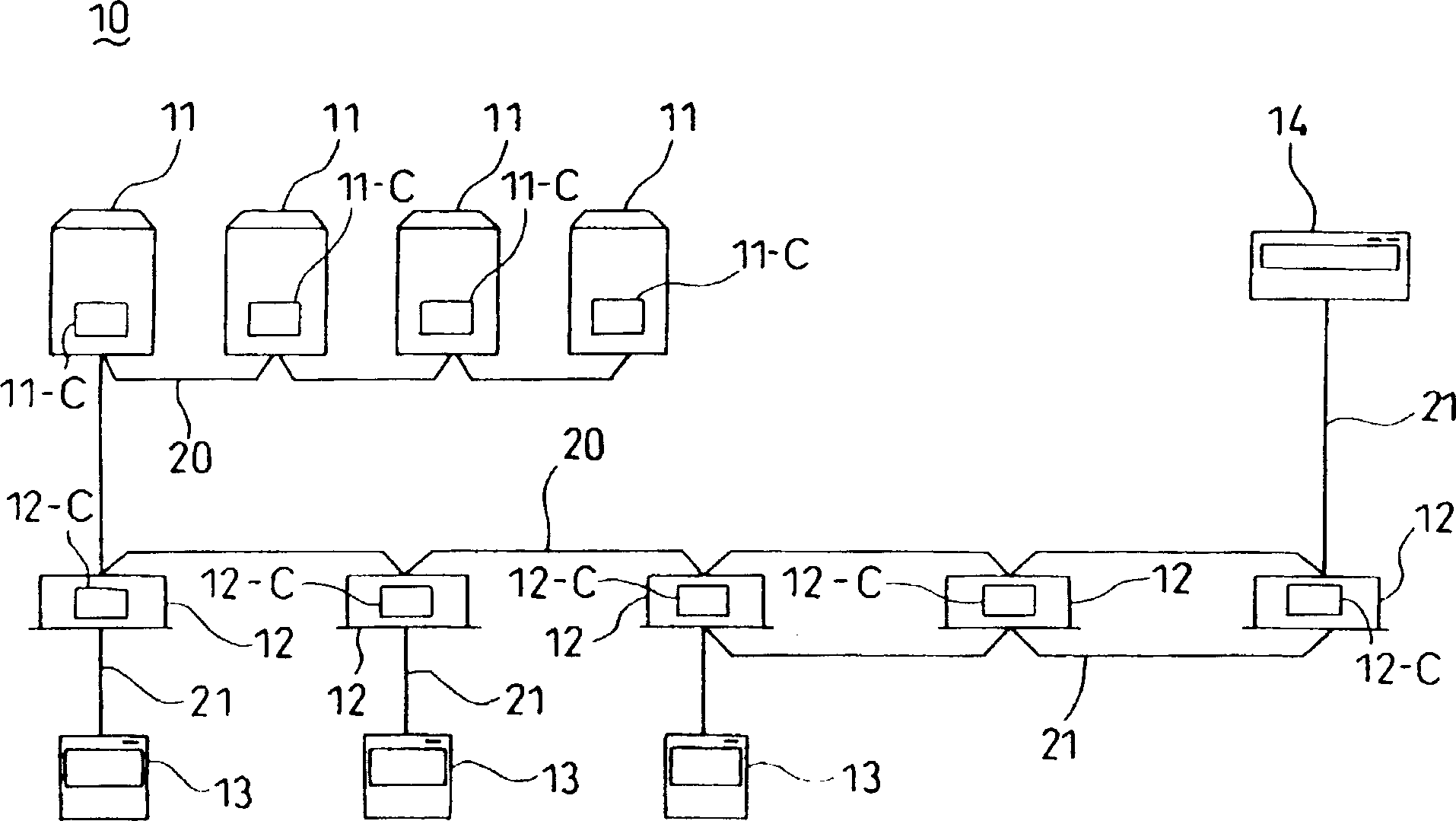
[0096] figure 2 Shown is a control system of an air conditioner (10) equipped with four outdoor units (11, 11, ...) and a plurality of indoor units (12, 12, ...). The four outdoor control units (11-C, 11-C, ...) that control the outdoor units (11, 11, ...) are sequentially connected to the control A plurality of indoor control units (12-C, 12-C, ...) of each indoor unit (12, 12, ...), between the outdoor control units (11-C, 11-C, ...) and The indoor control units (12-C, 12-C, . . . ) send and receive air-conditioning control information signals.

[0097] In addition, the indoor control units (12-C, 12-C, ...) are divided into multiple air-conditioning groups, and each air-conditioning group is connected to a remote controller (13) through a communication line (21) composed of two signal lines. , sending and rece...


PUM


Abstract

Control units are connected to each other through a communication line. Discharging resistors for releasing the residual charge on the line are provided. Each control unit is provided with a DC superimposing circuit which applies a DC voltage and outputs a specific number signal to the line from the circuit. The control unit is also provided with a polarity selecting circuit having a negative resistance characteristic that the electric current flowing through the circuit increases as the voltage applied drops, and a voltage discriminating circuit which detects the terminal voltage of the circuit. The control unit detects the voltage of communication line and determines whether its own control unit is a master unit or a slave unit utilizing output signals from the voltage discriminating circuit and a polarity discriminating circuit.

Description

technical field [0001] The present invention relates to an operation control device of an air conditioner, in particular to an operation control device adopting an AMI (Alternate Sign Inversion) communication method. Background technique [0002] In conventional air conditioners, the signal transmission method between the indoor unit and the outdoor unit employs, for example, the AMI communication method. [0003] In this AMI communication method, data is transmitted with a predetermined polarity, and if the polarity is not matched due to a wrong connection, there is a problem that the data content cannot be read correctly. [0004] That is to say, for example, if A-device and B-device connected through a communication line are connected with opposite polarities, when the two devices send data at the same time, in the communication line, the data signals of A-device and B-device overlap and overlap each other. Offset, the voltage level of the communication line becomes 0 le...

Claims


Application Information

Patent Timeline
IPC IPC(8): H02J13/00H04Q9/14
CPCH02J13/0044H04Q9/14Y10T307/931Y10T307/461Y10T307/839H02J13/00009Y04S40/121Y02B90/20Y02E60/00
Inventor 冈野贵史鎌房功二川上久寿
Owner DAIKIN IND LTD
Why Eureka
Try Eureka