
Multifunctional aspirator head for ear-nose-throat head-neck surgery

A suction head, ear, nose and throat technology, applied in the direction of suction equipment, drug equipment, anatomical equipment, etc., can solve problems such as easy blockage of the suction head

Inactive Publication Date: 2021-12-10
新余市人民医院
View PDF0 Cites 1 Cited by
  • Summary
  • Abstract
  • Description
  • Claims
  • Application Information

AI Technical Summary

Problems solved by technology

[0004] The technical problem to be solved by the present invention is to overcome the existing defects and provide a multifunctional suction head for otolaryngology head and neck surgery to solve the problem of easy blockage inside the suction head proposed in the above background technology

Method used


Image

  • Multifunctional aspirator head for ear-nose-throat head-neck surgery
  • Multifunctional aspirator head for ear-nose-throat head-neck surgery
  • Multifunctional aspirator head for ear-nose-throat head-neck surgery

Examples


Embodiment 1

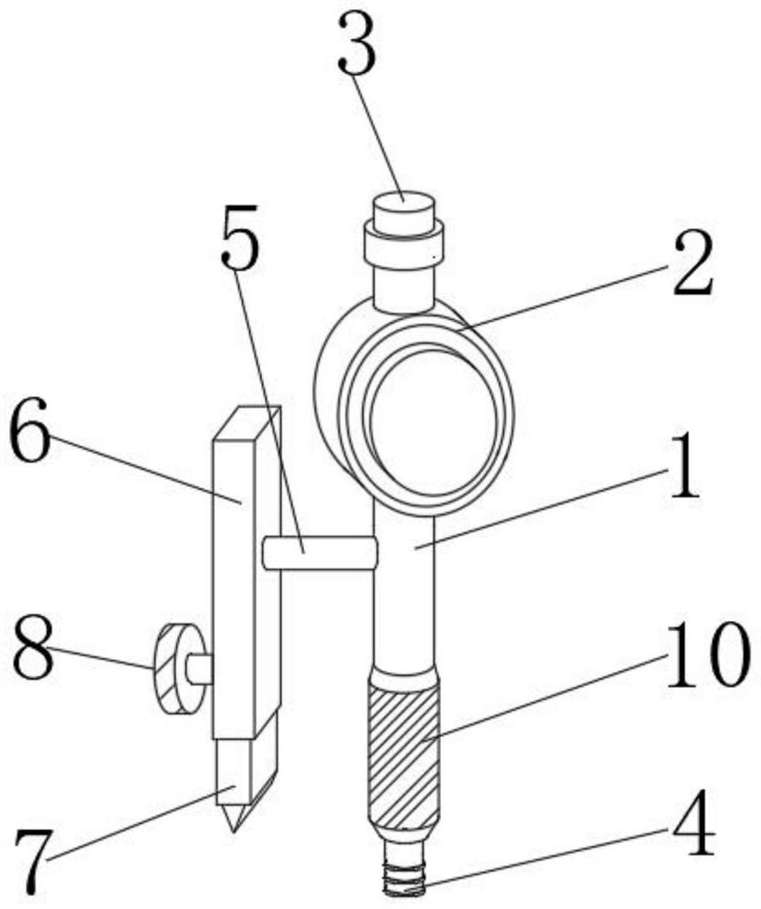
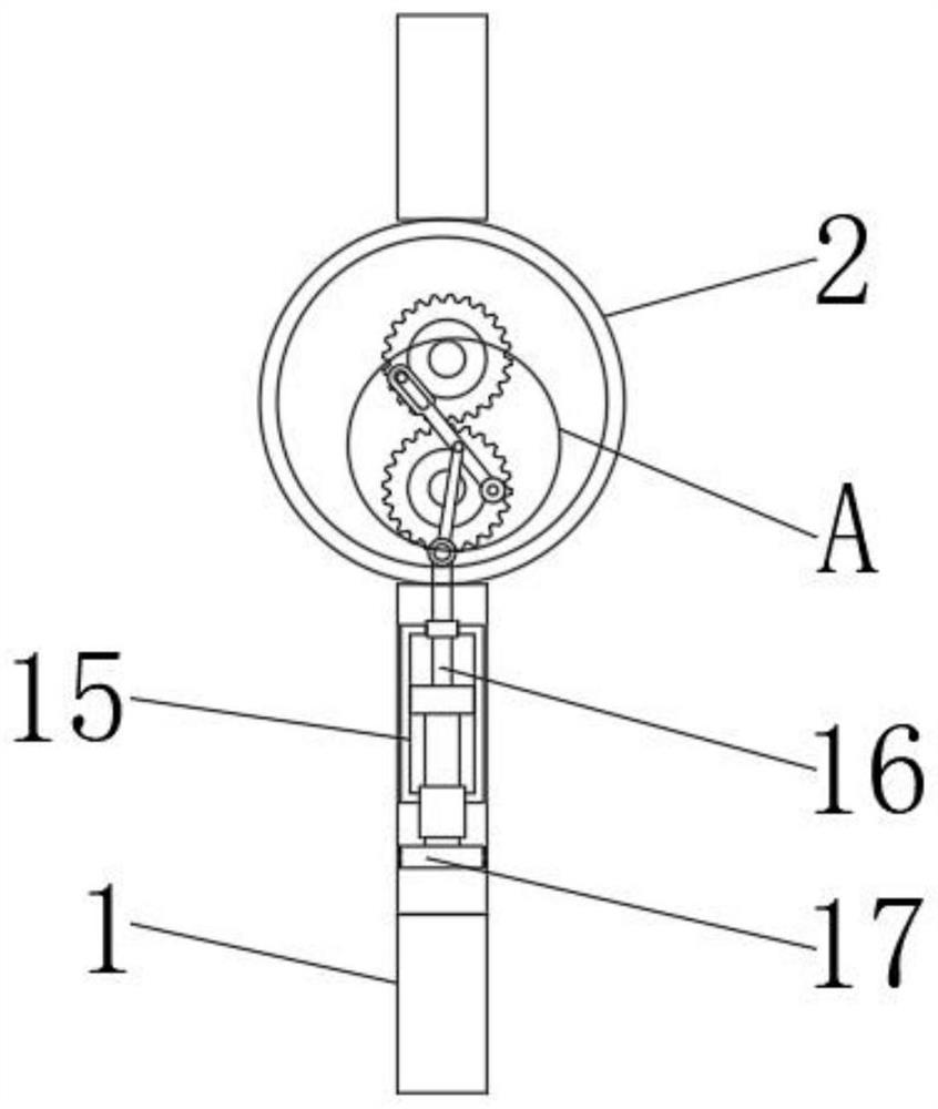
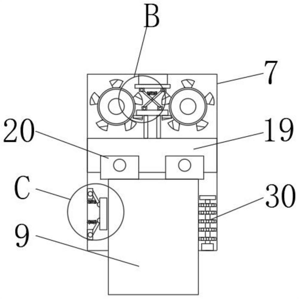
[0043] A multifunctional suction head for otolaryngology head and neck surgery, comprising a suction head body 1, a fixing plate 6, a cutting plate 7, a cleaning block 17, a rotating disc 21, a vibrating disc 30 and a suction body 31, the suction body 1 is provided with a suction connector 3 at the top, a connector 4 is provided at the lower end of the suction head body 1, a protective ring 2 is provided at the upper end of the suction head body 1, and a driving gear 11 is provided inside the protective ring 2, and one side of the driving gear 11 is connected by transmission. There is a micro motor, the surface of the other side of the driving gear 11 is rotatably connected with a rotating rod 13, the other end of the rotating rod 13 is connected to the side of the driven gear 12, and the middle side of the rotating rod 13 is rotatably connected with a rotating rod 2 14. The other end of the rotating rod 14 is fixedly connected with a piston rod 16, and the other end of the pis...

Embodiment 2

[0045] A multifunctional suction head for otolaryngology head and neck surgery, comprising a suction head body 1, a fixing plate 6, a cutting plate 7, a cleaning block 17, a rotating disc 21, a vibrating disc 30 and a suction body 31, the suction body 1 is provided with a suction connector 3 at the top, a connector 4 is provided at the lower end of the suction head body 1, a protective ring 2 is provided at the upper end of the suction head body 1, and a driving gear 11 is provided inside the protective ring 2, and one side of the driving gear 11 is connected by transmission. There is a micro motor, the surface of the other side of the driving gear 11 is rotatably connected with a rotating rod 13, the other end of the rotating rod 13 is connected to the side of the driven gear 12, and the middle side of the rotating rod 13 is rotatably connected with a rotating rod 2 14. The other end of the rotating rod 14 is fixedly connected with a piston rod 16, and the other end of the pis...


PUM


Abstract

The invention discloses a multifunctional aspirator head for ear-nose-throat head and neck surgery, which comprises an aspirator head body, a fixing plate, a cutting plate, a cleaning block, a rotating disc, a vibrating disc and an aspirator body, an aspirator joint is arranged at the top end of the aspirator head body, and a connector is arranged at the lower end of the aspirator head body. Through an arranged driving gear, the driving gear can be driven to rotate through a micro motor, on one hand, a first rotating rod on the surface of the driving gear can rotate, on the other hand, clamping teeth on the surface of the driving gear can be meshed with clamping teeth on the surface of a driven gear, so that the driven gear can rotate, through cooperation of a first rotating rod and a second rotating rod, a piston rod at the other end of the second rotating rod can drive a cleaning block to move up and down in the aspirator body in a reciprocating mode, a protruding scraping piece is arranged on the surface of the outer side of the cleaning block, and the cleaning block drives the protruding scraping piece to move in the aspirator head body. and dirt blocked in the aspirator head body can be discharged to the outside.

Description

technical field [0001] The invention belongs to the technical field of medical instruments, in particular to a multifunctional aspirator head for otolaryngology head and neck surgery. Background technique [0002] The organs of the ear, nose, throat, head and neck are closely related to each other in terms of anatomical structure, physiological function and the occurrence and development of diseases. In order to clearly identify its normal shape and pathological manifestations, special lighting devices and inspection equipment must be used. Therefore, in the development of modern medicine, it has gone through a process from division to integration. The development of otology was earlier, and then rhinology and laryngology were also separated one after another; around the middle of the 19th century, otolaryngology was merged into an independent medical discipline. [0003] During otolaryngology head and neck surgery, it is necessary to install the aspirator head on the aspir...

Claims


Application Information

Patent Timeline
IPC IPC(8): A61M1/00A61B17/3209
CPCA61B17/3209A61M2209/10
Inventor 张丽卫刘欣李敏朱昌华黄军付小刚方利达
Owner 新余市人民医院
Learn More