
Metal material processing system

A processing system and metal material technology, applied in the field of processing, can solve problems such as low reliability, obstruction, rough surface of parts, etc., to achieve the effect of ensuring a flat surface, simple and direct algorithm, and improving reliability

Inactive Publication Date: 2021-12-10
QINGDAO UNIV
View PDF0 Cites 0 Cited by
  • Summary
  • Abstract
  • Description
  • Claims
  • Application Information

AI Technical Summary

Problems solved by technology

There are many problems in the current deposition processing of most metal materials: (1) During the layer-by-layer deposition process, if the process deviation is not corrected in time, the defects will propagate to the subsequent layers, thereby affecting the functional integrity of the part (fatigue properties, strength properties, geometric integrity) lead to low reliability and low quality, which is not conducive to its large-scale commercialization; (2) due to the solidification form of metal droplets and the step effect, parts deposited by metal droplets usually have rough surfaces, while rough The surface barrier technology is used to manufacture parts with high-quality surface finish requirements, especially some microwave devices, such as waveguides and horn antennas, which require smooth inner surfaces to ensure the propagation of electromagnetic waves; (3) in order to be able to control droplets generation requires very precise measurement and control of jetting properties, such as droplet velocity and droplet volume, and precise droplet capture is currently lacking

Method used


Image

  • Metal material processing system
  • Metal material processing system
  • Metal material processing system

Examples


Embodiment Construction

[0012] The present invention will be further described below with reference to the accompanying drawings and embodiments.

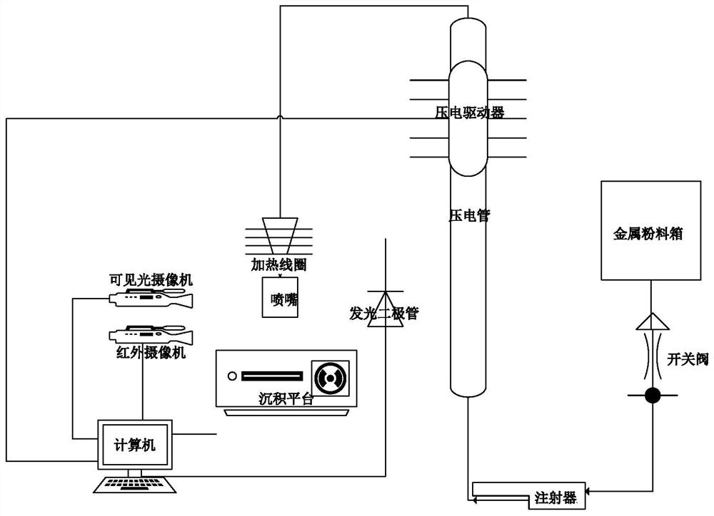
[0013] Reference to embodiments of the present invention Figure 1-2 shown.

[0014] A metal material processing system, including a visible light camera, an infrared camera, a light-emitting diode, a deposition platform, a computer, a piezoelectric driver, a nozzle, an induction heating coil, a piezoelectric tube, a syringe, a metal powder box and an on-off valve, a metal powder box Under the push of the syringe, the metal powder box enters the piezoelectric tube. By adjusting the syringe, the metal powder is pumped into the piezoelectric tube. The liquid level in the piezoelectric tube will reflect the pressure applied to the metal powder. After the metal powder box in the electric tube enters the nozzle, it forms droplets under the action of the induction heating coil, which drop to the interface on the deposition platform, and the deposition platform...


PUM


Abstract

A metal material processing system comprises a visible light camera, an infrared camera, a light-emitting diode, a deposition platform, a computer, a piezoelectric driver, a nozzle, an induction heating coil, a piezoelectric tube, an injector, a metal powder box and a switch valve, wherein the liquid level in the piezoelectric tube reflects the pressure applied to metal powder, and after the metal powder in the piezoelectric tube enters the nozzle, liquid drops are formed under the action of the induction heating coil and drop to an interface on the deposition platform; the computer collects the temperature of the liquid drops through the infrared camera and controls the induction heating coil to heat the nozzle so that the metal powder can be changed into metal liquid, and the computer controls the propelling pressure of the injector; the visible light camera captures an image jetted by the nozzle, and the computer performs image processing and analysis based on the jetted image; and dynamic liquid drop behaviors are obtained accordingly from a series of images.

Description

technical field [0001] The invention belongs to the processing field, and particularly relates to a metal material processing system. Background technique [0002] Deposition processing using molten metals enables the construction of complex objects with a wide variety of materials and functions, opening enormous opportunities for a wide range of applications including the aerospace, automotive, defense and biomedical industries. There are many problems in the current deposition processing of most metal materials: (1) During the layer-by-layer deposition process, if the process deviation is not corrected in time, the defects will propagate to the subsequent layers, thus affecting the functional integrity of the part (fatigue characteristics, strength characteristics, (2) Due to the solidification morphology of metal droplets and the step effect, parts deposited by metal droplets usually have a rough surface, which is not conducive to large-scale commercialization. The surfa...

Claims


Application Information

Patent Timeline
Patent Type & Authority Applications(China)
IPC IPC(8): B22F12/00B22F12/90B22F12/53B22F10/22B22F10/85B22F10/31B33Y10/00B33Y30/00B33Y50/02G06N3/04
CPCB22F12/00B22F12/90B22F12/53B22F10/22B22F10/85B22F10/31B33Y10/00B33Y30/00B33Y50/02G06N3/04Y02P10/25
Inventor 王怀志
Owner QINGDAO UNIV
Features
  • Generate Ideas
  • Intellectual Property
  • Life Sciences
  • Materials
  • Tech Scout
  • Unparalleled Data Quality
  • Higher Quality Content
  • 60% Fewer Hallucinations
Learn More