A pneumatic pipeline conveyor

A technology of pneumatic pipelines and conveyors, which is applied in the direction of conveyors, conveying bulk materials, mixers, etc., can solve the problems of changing the conveying position, which is laborious and laborious, and cannot be guaranteed, so as to save manpower, use and maintain low costs, and save electricity. Effect

Active Publication Date: 2022-03-08
SHANDONG LONGCHANG INTELLIGENT TECH CO LTD
View PDF0 Cites 0 Cited by
  • Summary
  • Abstract
  • Description
  • Claims
  • Application Information

AI Technical Summary

Problems solved by technology

In addition, the materials are transported by conventional conveyor belts, taking up space, and changing the conveying position is laborious, and it is impossible to guarantee the ideal state of dust-free and dust-free conveying of various powdery materials.

Method used


Image

  • A pneumatic pipeline conveyor
  • A pneumatic pipeline conveyor
  • A pneumatic pipeline conveyor

Examples


Embodiment 1

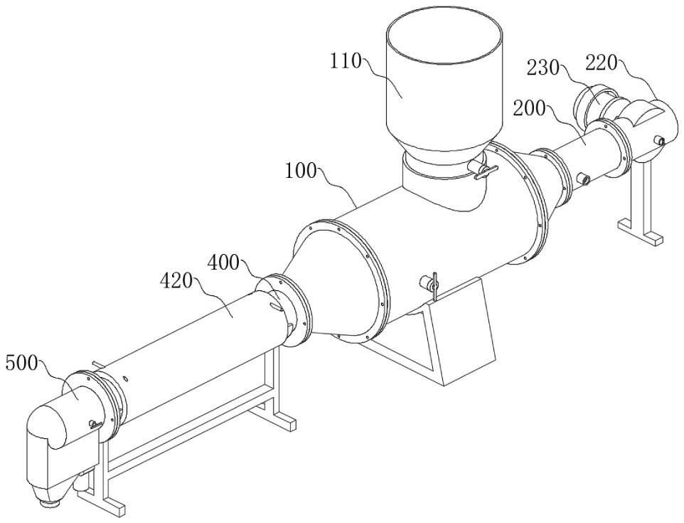
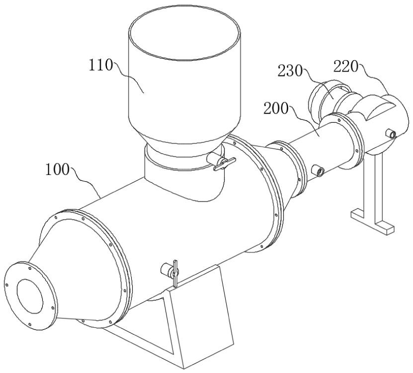
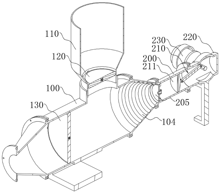
[0049] see Figure 1-Figure 17 As shown, the present invention provides a pneumatic pipeline conveyor, which includes a mixing tube 100 that can mix different types of particles and a pneumatic tube 200 that is used to inject air into the interior of the mixing tube 100, that is, using air flow to mix different types of particles. Different types of particles are mixed and then transported. The mixing pipe 100 is provided with an injection cylinder 110 near the top of its rear end, which is used to inject chemical particles such as polypropylene, PET, ABS, PVC, etc., so as to realize mechanized and automatic material delivery, which can reduce labor intensity and save manpower. And during the conveying process, the technological operations of mixing, drying and screening can be carried out at the same time. The bottom of the injection cylinder 110 is radially rotatably connected with a cylinder valve block 120 for partially blocking the injection cylinder 110 to prevent the m...


PUM


Abstract

The invention discloses a pneumatic pipeline conveyor, which comprises a material mixing tube and a pneumatic tube for injecting air into the inside of the material mixing tube provided at the rear end of the material mixing tube. The rear end of the pipe is provided with an air blowing mechanism, the front end of the mixing pipe is connected with a drying pipe, and the outer side of the drying pipe is provided with a spiral electric heating pipe along its axial direction, and the front end of the drying pipe is connected with a The material distribution pipe is connected with a separation pipe at the bottom of the material distribution pipe, and one end of the material distribution pipe is closed and a flow diversion mechanism is arranged inside the opening end of the material distribution pipe. In the present invention, through the provided mixing pipe and the pneumatic pipe that continuously ventilates the interior, various materials inside can be fully mixed, and when the mixing pipe is opened, the materials can be transported airtightly through the pipeline to the It is evenly dried in the drying pipe, and then transported to the material distribution pipe to be screened for light and heavy materials, which makes the conveying process realize mechanization and automation, saves manpower, and has practical value.

Description

technical field [0001] The invention relates to the technical field of chemical powder transportation, in particular to a pneumatic pipeline conveyor. Background technique [0002] With the improvement of national environmental protection standards and the enhancement of awareness of comprehensive utilization, it has become the current development trend to realize mixing, drying and screening of materials in a closed environment, so as to avoid pollution of the environment and air in each processing link. In addition, conventional conveyor belts are used to convey materials, which takes up space, and changing the conveying position is labor-intensive, which cannot guarantee the ideal state of dust-free and dust-free conveying of various powdery materials. Contents of the invention [0003] The purpose of the present invention is to provide a pneumatic pipeline conveyor to solve the problems raised in the above-mentioned background technology. [0004] In order to achieve ...

Claims


Application Information

Patent Timeline
Patent Type & Authority Patents(China)
IPC IPC(8): B65G53/34B65G69/20B65G53/66B07B7/01B01F33/40
CPCB65G53/34B65G69/20B65G53/66B07B7/01
Inventor 张现来赵银堂杨森
Owner SHANDONG LONGCHANG INTELLIGENT TECH CO LTD
Why Eureka
Try Eureka