Temperature drop type anti-explosion early-warning hydraulic oil cylinder

A hydraulic oil cylinder and temperature drop technology, applied in the field of hydraulic oil cylinders, can solve the problems of high cylinder explosion risk, cylinder explosion, difficult staff and other problems, and achieve the effect of ensuring cooling effect, preventing cylinder explosion and improving cooling efficiency.

Active Publication Date: 2021-12-10
杭州谦泰五金机械制造有限公司
View PDF15 Cites 2 Cited by
  • Summary
  • Abstract
  • Description
  • Claims
  • Application Information

AI Technical Summary

Problems solved by technology

[0003] The hydraulic cylinder can provide high-frequency and large thrust. During the working process of the hydraulic cylinder, there is friction between the hydraulic oil and the cylinder wall. At the same time, the friction between the hydraulic oil and the cylinder wall will generate a lot of heat. At the same time, under the condition of heavy load, the hydraulic oil will be compressed to a certain extent, and the viscosity coefficient of the hydraulic oil will also increase accordingly. The friction generated during work will If it is further increased, a large amount of heat will be generated. If the heat is dissipated only through the thermal conductivity of the hydraulic cylinder itself, it will be difficult to dissipate the heat quickly, and if the staff does not find the abnormality in time, the hydraulic cylinder will continue to operate. Cylinder explosion is prone to occur when working under high temperature
[0004] How to design a temperature-dropping explosion-proof early warning hydraulic cylinder that can efficiently cool down, effectively avoid the occurrence of cylinder explosion, and can issue an alarm at high temperature has become a solution to the existing technology that generates a lot of heat during high-frequency operation or under load. , There is a high risk of cylinder explosion, and it is difficult for staff to find abnormal problems in time

Method used


Image

  • Temperature drop type anti-explosion early-warning hydraulic oil cylinder
  • Temperature drop type anti-explosion early-warning hydraulic oil cylinder
  • Temperature drop type anti-explosion early-warning hydraulic oil cylinder

Examples


Embodiment 1

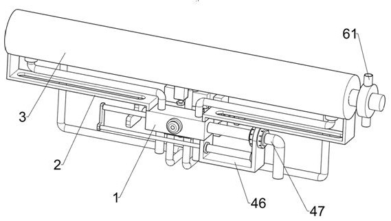
[0040]Temperature drop explosion-proof early warning hydraulic cylinder, such as figure 1 , figure 2 , image 3 , Figure 4 , Figure 5 , Figure 6 , Figure 7 , Figure 8 , Figure 9 , Figure 10 , Figure 11 and Figure 12 As shown, it includes a liquid guide frame 1, a support plate frame 2, a hydraulic cylinder 3, a hydraulic drive part 4, a pressure relief part 5 and a double-pipe cooling part 6, and a pair of support plate frames 2 are fixedly connected to the top of the liquid guide frame 1. A hydraulic cylinder 3 is fixedly connected between the two support plates 2, and a hydraulic drive part 4 is provided on the liquid guide frame 1, and the hydraulic drive part 4 is used to drive the hydraulic oil to flow in the hydraulic cylinder 3, and the hydraulic cylinder 3 is provided with a drain The pressure component 5 and the pressure relief component 5 are used to relieve pressure when the pressure in the hydraulic cylinder 3 is too large. The hydraulic drive c...

Embodiment 2

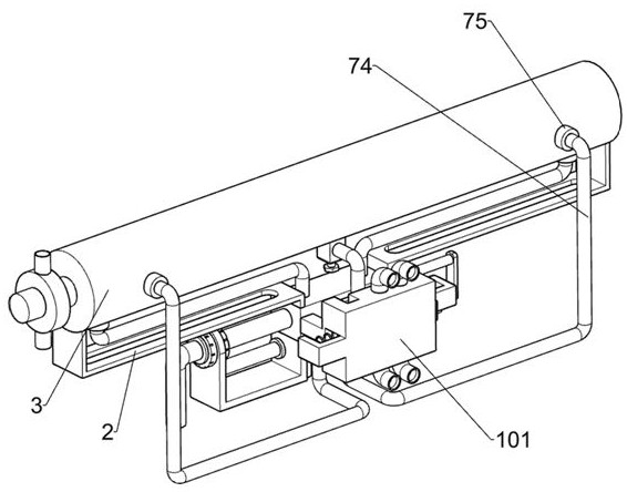
[0048] On the basis of Example 1, such as Figure 13 Shown, also comprise explosion-proof component 7, and explosion-proof component 7 is located at piston plate 45 inner tops, and explosion-proof component 7 is used for preventing explosion cylinder phenomenon from taking place, and explosion-proof component 7 includes induction rod 71, movable rod 72, back-moving spring 73, return The liquid pipe 74 and the solenoid valve 75, the upper and lower parts of the piston plate 45 are fixedly connected with a sensing rod 71, and the sensing rod 71 is used to sense pressure information, and a pair of movable rods 72 are slidably connected to the upper and lower parts of the piston plate 45. , the adjacent movable rod 72 is located on the left and right sides of the sensing rod 71, and a reset spring 73 is connected between the movable rod 72 and the sensing rod 71. Frame 1 is connected, and the liquid return pipe 74 is connected to the solenoid valve 75 by welding on the side close ...

Embodiment 3

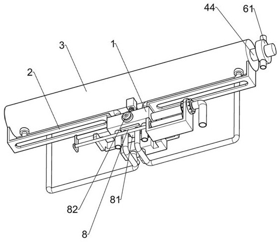
[0051] On the basis of Example 2, such as image 3 As shown, a warning part 8 is also included. The warning part 8 is arranged on the liquid guide frame 1. The warning part 8 is used to warn the staff to take corresponding treatment when the hydraulic oil temperature is high. The warning part 8 includes a negative temperature coefficient thermal The sensitive resistance plate 81 and the buzzer 82, the lower part of the outer side of the liquid guide frame 1 is fixedly connected with the negative temperature coefficient thermistor plate 81 for sensing the information of temperature rise, the liquid return pipe 74 and the negative temperature coefficient thermistor plate 81 Fixed connection, a buzzer 82 is fixed on the outer front side of the liquid guide frame 1, and the buzzer 82 is used to issue an alarm.

[0052] When the temperature of the hydraulic oil flowing through the liquid guide frame 1 through the liquid return pipe 74 is high, the negative temperature coefficient t...


PUM


Abstract

The invention relates to the field of hydraulic oil cylinders, in particular to a temperature drop type anti-explosion early-warning hydraulic oil cylinder which comprises a liquid guide frame, supporting plate frames, a hydraulic oil cylinder body, a hydraulic driving component and the like, wherein one pair of supporting plate frames is fixedly connected to the top of the liquid guide frame, the hydraulic oil cylinder is fixedly connected between the two supporting plate frames, and the hydraulic driving component is arranged on the liquid guide frame. Through cooperation of a U-shaped backflow tube and devices on the U-shaped backflow tube, cooling liquid circulates in the U-shaped backflow tube, heat exchange is conducted between the cooling liquid and hydraulic oil in the hydraulic oil cylinder, and the cooling liquid can take away heat generated when the hydraulic oil cylinder operates, so that the hydraulic oil in the hydraulic oil cylinder can be cooled, cylinder explosion caused by too high temperature is prevented, and the purpose of effectively cooling is achieved.

Description

technical field [0001] The invention relates to the field of hydraulic oil cylinders, in particular to a temperature-drop type explosion-proof early warning hydraulic oil cylinder. Background technique [0002] The hydraulic cylinder is a hydraulic actuator that converts hydraulic energy into mechanical energy and performs linear reciprocating motion. It has a simple structure and reliable operation. The power source of the hydraulic cylinder is the thrust of hydraulic oil. There is no deceleration device, and there is no transmission gap, and the movement is smooth, so it is widely used in various mechanical hydraulic systems. [0003] The hydraulic cylinder can provide high-frequency and large thrust. During the working process of the hydraulic cylinder, there is friction between the hydraulic oil and the cylinder wall. At the same time, the friction between the hydraulic oil and the cylinder wall will generate a lot of heat. At the same time, under the condition of heavy...

Claims


Application Information

Patent Timeline
Patent Type & Authority Applications(China)
IPC IPC(8): F15B15/14F15B19/00F15B20/00G01K7/22
CPCF15B15/14F15B15/1485F15B15/149F15B15/1423F15B19/005F15B20/00G01K7/22
Inventor 王耀珍
Owner 杭州谦泰五金机械制造有限公司
Why Eureka
Try Eureka