Optical waveguide structure and near-eye display

A technology of optical waveguide and optical waveguide sheet, which can be applied in the direction of optical waveguide, optics, instruments, etc., and can solve the problems of poor imaging effect and so on.

Pending Publication Date: 2021-12-10
宁波舜宇奥来技术有限公司
View PDF10 Cites 9 Cited by
  • Summary
  • Abstract
  • Description
  • Claims
  • Application Information

AI Technical Summary

Problems solved by technology

[0005] The main purpose of the present invention is to provide an optical waveguide structure and a near-eye display to solve the problem of poor imaging effect in the optical waveguide structure in the prior art

Method used


Image

  • Optical waveguide structure and near-eye display
  • Optical waveguide structure and near-eye display
  • Optical waveguide structure and near-eye display

Examples


Embodiment 1

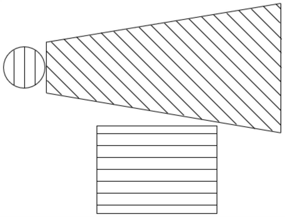
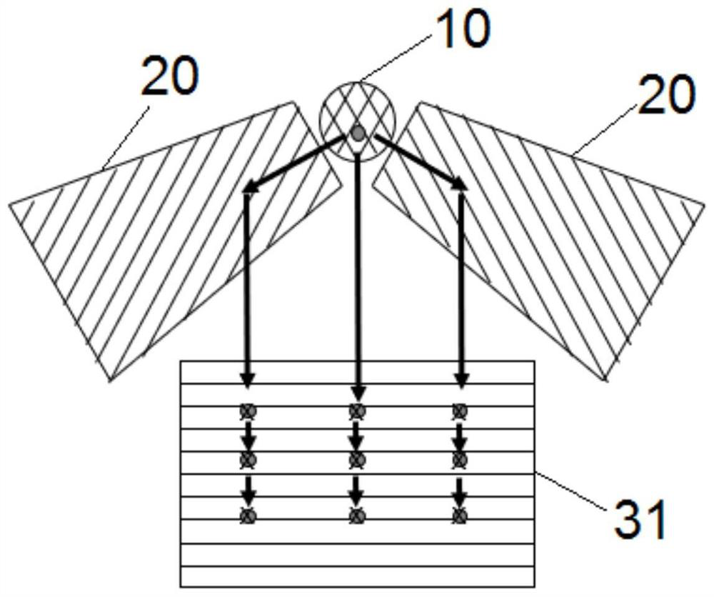
[0033] Such as Figure 4 to Figure 5 As shown, the optical waveguide structure includes an optical waveguide, an in-coupling grating 10, a turning grating 20 and an out-coupling grating, the in-coupling grating 10 is arranged on the optical waveguide, the in-coupling grating 10 is a two-dimensional grating, and the in-coupling grating 10 is used to The light emitted by the external light source assembly is coupled into the optical waveguide sheet; there are multiple turning gratings 20, and the plurality of turning gratings 20 include at least two turning gratings 20, and the two turning gratings 20 are respectively arranged on the same or different sides of the optical waveguide sheet. on the surface, and the projections of the two turning gratings 20 on the optical waveguide are set at an angle, the turning grating 20 is used to receive the light coupled into the grating 10; the outcoupling grating is used to receive the light coupled into the grating 10 and the turning grati...

Embodiment 2

[0060] The difference from the first embodiment is that the coupling grating 10 is different, and the arrangement of the turning grating 20 is different.

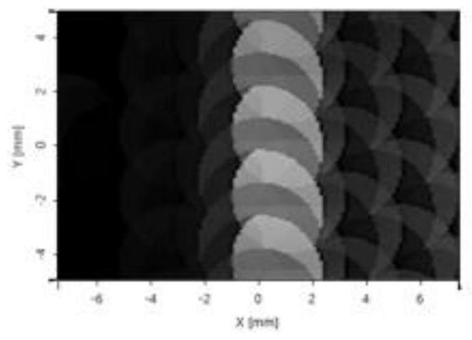
[0061] Such as Figure 6 and Figure 7 As shown, the two deflection gratings 20 are arranged in a straight line on the optical waveguide plate, and the coupling-in grating 10 is located between the projections of the two deflection gratings 20 on the optical waveguide plate. At this time, the included angle between the first grating line direction 11 coupled into the grating 10 and the second grating line direction 12 is a right angle. Figure 6 The normalized variance within the middle eye box is 62.7%.

[0062] Compared with Embodiment 1, this embodiment reduces the occupied area of ​​the coupling-in grating 10, the turning grating 20, and the coupling-out grating on the optical waveguide sheet, ensuring miniaturization. The intensity effect is better than that of the first embodiment, and the light intensity effect of...


PUM


Abstract

The invention provides an optical waveguide structure and a near-eye display. The optical waveguide structure comprises an optical waveguide sheet, a coupled grating which is a two-dimensional grating, a plurality of turning gratings, and a plurality of coupling-out gratings; the plurality of turning gratings at least comprise two turning gratings, the two turning gratings are respectively arranged on the same or different surfaces of the optical waveguide sheet, the projections of the two turning gratings on the optical waveguide sheet are arranged at an angle, and the turning gratings are used for receiving light of a coupling-in grating; the coupling-out gratings are used for receiving light of the coupling-in grating and the turning grating and coupling the light out of the optical waveguide sheet, the multiple coupling-out gratings at least comprise a first coupling-out grating and a second coupling-out grating, the first coupling-out grating is a one-dimensional grating, the second coupling-out grating is a two-dimensional grating, the first coupling-out grating and the second coupling-out grating are located on different surfaces of the optical waveguide sheet, and the projection of the first coupling-out grating and the projection of the second coupling-out grating on the optical waveguide sheet coincide. The problem that an optical waveguide structure in the prior art is poor in imaging effect is solved.

Description

technical field [0001] The invention relates to the technical field of optical imaging equipment, in particular to an optical waveguide structure and a near-eye display. Background technique [0002] With the development of society and the continuous innovation of science and technology, virtual reality (VR), augmented reality (AR) and mixed reality (MR) have gradually entered people's lives, among which optical waveguide technology is indispensable in AR augmented reality In the first step, it uses a flat optical waveguide with a diffraction grating to transmit the image emitted by the light source component and expand the pupil to the human eye, so that the user can observe the virtual image superimposed on the world projected by the light source component while seeing the real world. [0003] There are a variety of design schemes on the market, but the display effect is not ideal. The reason is that the transmission of light in the optical waveguide will cause loss of lig...

Claims


Application Information

Patent Timeline
Patent Type & Authority Applications(China)
IPC IPC(8): G02B6/10G02B5/18G02B27/01
CPCG02B6/10G02B5/1819G02B27/0172G02B2027/0178
Inventor 高一峰熊羚鹤孙理斌汪杰陈远
Owner 宁波舜宇奥来技术有限公司
Why Eureka
Try Eureka