High-temperature superconducting magnet and preparation method thereof

A high-temperature superconducting and magnet technology, applied in superconducting magnets/coils, magnetic objects, coil manufacturing, etc., can solve problems such as thermal stress differences, inability to make full use of the strength of each turn of superconducting strip, and cold shrinkage of superconducting coils

Pending Publication Date: 2021-12-10
WUHAN MARINE ELECTRIC PROPULSION RES INST CHINA SHIPBUILDING IND CORP NO 712 INST
View PDF0 Cites 1 Cited by
  • Summary
  • Abstract
  • Description
  • Claims
  • Application Information

AI Technical Summary

Problems solved by technology

Under operating conditions, on the one hand, due to the difference in material thermal conductivity and interface contact thermal resistance, there is inevitably a temperature gradient inside the magnet. If the temperature gradient is large, the superconducting magnet will generate a large amount of heat in a low-temperature environment. On the other hand, when the number of turns of the superconducting coil is large, the low-temperature environment will cause the superconducting coil to shrink coldly, which will lead to a large difference between the thermal stress of the inner-turn superconducting strip and the outer-turn superconducting strip, causing super The distribution of thermal stress inside the conductor coil is extremely uneven, so that the strength of each turn of superconducting tape cannot be fully utilized

Method used


Image

  • High-temperature superconducting magnet and preparation method thereof
  • High-temperature superconducting magnet and preparation method thereof
  • High-temperature superconducting magnet and preparation method thereof

Examples


Embodiment 1

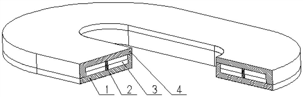
[0052] refer to Figure 1 to Figure 8 A basic embodiment of the invention is shown.

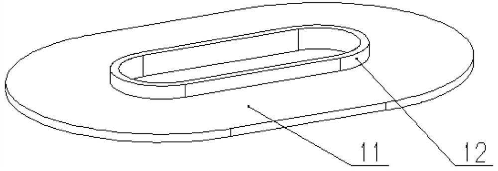
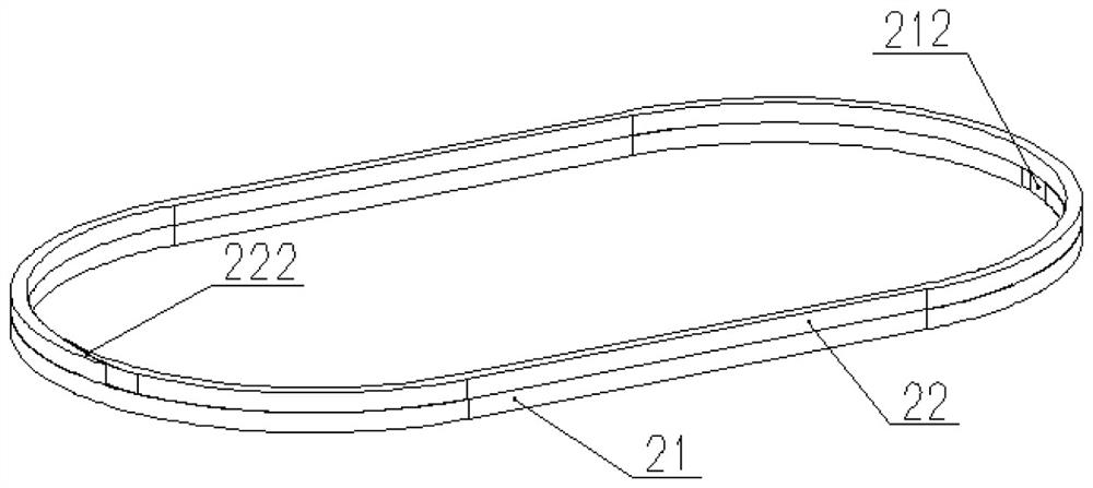
[0053] A high-temperature superconducting magnet disclosed by the present invention is composed of a superconducting coil 3, a magnet upper cover plate 4, a magnet lower bottom plate 1, and a lower spacer 21 and an upper spacer 22 arranged up and down. The superconducting coil 3 consists of Composed of two sub-superconducting coils, such as Figure 5 The first sub-superconducting coil 31 and the second sub-superconducting coil 32 shown are connected in series through a superconducting tape, wherein the first sub-superconducting coil 31 is composed of a single-cake coil 311 and a single-cake coil 312. The spacer 21 is separated, and is connected in series by the superconducting tape 313 that passes through the gap 212, and the second sub-superconducting coil 32 is composed of a single cake coil 321 and a single cake coil 322, separated by the upper spacer 22, and The superconducting strips 3...

Embodiment 2

[0055] A method for preparing a high-temperature superconducting magnet disclosed by the present invention, the superconducting coil is composed of a sub-superconducting coil, and when each sub-superconducting coil contains M+1 single-cake coils, the steps of the preparation method are as follows:

[0056] Step 1: Machining the upper cover plate 4 of the magnet, the lower bottom plate 1 of the magnet and M spacers 2 with different inner diameters, and cleaning the oil and dust on the surface of each component.

[0057] Step 2, install the M spacers 2 on the bottom plate 1 of the magnet, with drilled pin holes, and mark them.

[0058] Step 3, install and fix the magnet upper cover plate 4 on the magnet lower base plate 1 equipped with the spacer 2, equip drill pin holes, and make marks.

[0059] Step 4, remove the upper cover plate 4 of the magnet, the lower bottom plate 1 of the magnet and the M spacers 2, and clean the oil and dust on the surface of each component again.

[...

Embodiment 3

[0066] A method for preparing a high-temperature superconducting magnet disclosed by the invention comprises the following steps:

[0067] In step 1, the upper cover plate 4 of the magnet, the lower bottom plate 1 of the magnet, the lower spacer 21 and the upper spacer 22 are machined, and oil and dust on the surface of each component are cleaned.

[0068] Step 2, install the lower spacer 21 and the upper spacer 22 on the lower bottom plate 1 of the magnet, equip drill pin holes, and make marks.

[0069] Step 3, install and fix the upper cover plate 4 of the magnet on the lower bottom plate 1 of the magnet equipped with the lower spacer 21 and the upper spacer 22, and drill pin holes for marking.

[0070] Step 4, remove the upper cover plate 4 of the magnet, the lower bottom plate 1 of the magnet, the lower spacer 21, and the upper spacer 22, and clean the oil and dust on the surface of each component again.

[0071] Step 5, adjust the winding tension value and loading method...


PUM


Abstract

The invention relates to a high-temperature superconducting magnet, which is composed of a magnet lower bottom plate, a magnet upper cover plate, a superconducting coil and M spacer blocks, wherein M is larger than or equal to 1, the magnet lower bottom plate is composed of a lower bottom plate body and a lower bottom plate boss, the magnet upper cover plate is composed of an upper cover plate body and an upper cover plate boss, each spacer block is of an annular structure with a notch,, and is connected with the magnet upper cover plate and the magnet lower bottom plate respectively, the superconducting coil is composed of one or two sub superconducting coils, each sub superconducting coil is composed of N single-cake coils, N is larger than or equal to 2, one spacer block is arranged between every two adjacent single-cake coils, and the two adjacent single-cake coils are connected in series into a whole through a superconducting strip. The invention also discloses a preparation method of the high-temperature superconducting magnet. According to the invention, great innovation is provided in the aspects of reducing the temperature difference in the magnet, reducing the overall thermal stress of the superconducting coil, fully utilizing the strength of each turn of superconducting tape, realizing the stress design of the superconducting coil and the like, and the high-temperature superconducting magnet is particularly suitable for being used in a high-temperature superconducting motor.

Description

technical field [0001] The invention belongs to the field of superconducting applications, and in particular relates to a high-temperature superconducting magnet and a winding method thereof. Background technique [0002] High-temperature superconducting motor refers to a new type of synchronous motor that replaces conventional copper coils with high-temperature superconducting coils. Due to the large AC loss of existing high-temperature superconducting materials under magnetic fields, high-temperature superconducting motors usually use superconducting excitation rotors and conventional stators. Topology of copper windings. [0003] High-temperature superconducting magnet is the main part of high-temperature superconducting motor to realize electromechanical energy conversion. It is composed of supporting parts and superconducting coils. It is usually machined with non-magnetic or weakly magnetically conductive metal materials such as oxygen-free copper, aluminum alloy or s...

Claims


Application Information

Patent Timeline
Patent Type & Authority Applications(China)
IPC IPC(8): H01F6/06H01F41/06
CPCH01F6/06H01F41/06
Inventor 周勇熊琪徐鸿李位勇
Owner WUHAN MARINE ELECTRIC PROPULSION RES INST CHINA SHIPBUILDING IND CORP NO 712 INST
Why Eureka
Try Eureka