Yarn pressing plate for colored spun yarn spinning machine
A technology for crimping boards and spinning machines, which is applied to spinning machines, spinning machines with continuous winding, textiles and papermaking, etc. It can solve the problems of easy damage to crimping boards, electric leakage of pay-off tubes, extrusion damage, etc. problems, to avoid potential safety hazards, improve safety, and increase life expectancy
- Summary
- Abstract
- Description
- Claims
- Application Information
AI Technical Summary
Problems solved by technology
Method used
Image
Examples
Embodiment 1
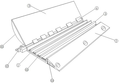
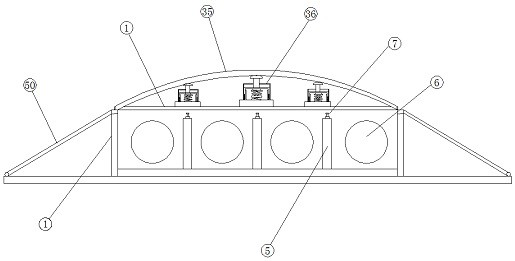
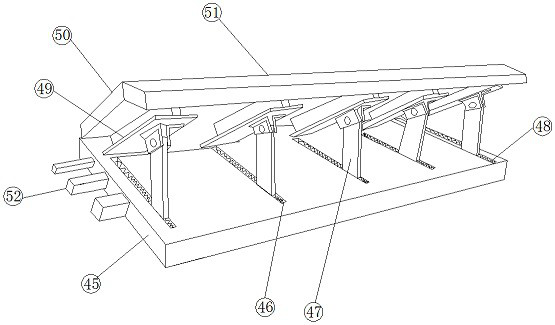
[0032] See Figure 1-7 , According to an embodiment of the present invention, a ribbon plate for a color spun spun, including a ribbon plate 1, and a compression device 2 is fixed to both sides of the line plate 1, and the ribbon plate 1. The top activity is provided with a cover 3, and the cover plate 3 is connected between the line plate 1 by the first connection hinge 4, and the internal activity of the ribbon plate 1 is inserted with a number of isolation plates 5. The discharge tube 6 is placed between the separator 5, the separator 5 fixedly covered with a pressure-resistant pressure cushioning device 7, which includes a connecting plate 8, which is connected. The plate 8 is fixed between the separator 5, and the connecting plate 8 is fixedly fixed from one side of the separator 5, and the internal bottom end of the first placement box 9 is fixed. Two support columns, the support post 10 is located on both sides of the first placement box 9, and a slider 11 is fixed between t...
Embodiment 2
[0035] See figure 1 and 6 For the cover 3, the cover plate 3 is connected to one side of the ribbon plate 1, and the arc shock absorbing plate 35 is passed between the cover plate 3. The damping device 36 is connected, the damper device 36 includes a fixed first base 37, and the fixed first base 37 is fixedly coupled to the cover plate 3, and the fixed first base 37 is fixed with a third placement. Box 38, both sides of the inner wall of the third placement box 38 fixed a slot 39, and the inner portion of the chute 39 is provided with a second movable rod 40, the second moving rod 40 away from the chute 39. One end is fixed to the first first movable plate 41, the second moving rod 40 is located in the middle of the first first movable plate 41 fixedly having a first damping spring 42, and the first damping spring 42 One end is fixed to the bottom of the third placement box 38, and the first first movable plate 41 is fixedly secured from one side of the first shock absorbing sprin...
Embodiment 3
[0038] See figure 1 and 2 For the slot 39, the bottom end of the inner portion of the chute 39 is fixed to the second damper spring 44, and the other end of the second damper spring 44 is fixed to the second moving rod 40 fixedly.
[0039] Through the above-described above scheme of the present invention, it is advantageous to function as a secondary shock absorber, and the second moving rod 40 causes the second moving rod 40 to cause a hit by the bottom portion of the slide 39, and causes the bottom damage of the slot 39, which greatly improves the slide 39. Safety.
PUM
 Abstract
Description
Claims
Application Information
 - R&D
- Intellectual Property
- Life Sciences
- Materials
- Tech Scout
- Unparalleled Data Quality
- Higher Quality Content
- 60% Fewer Hallucinations
Browse by: Latest US Patents, China's latest patents, Technical Efficacy Thesaurus, Application Domain, Technology Topic, Popular Technical Reports.
© 2025 PatSnap. All rights reserved.Legal|Privacy policy|Modern Slavery Act Transparency Statement|Sitemap|About US| Contact US: help@patsnap.com


