Suspended formwork structure of steel structure composite floor slab

A technology for steel structures and steel structure beams, which is applied in building construction, formwork/formwork/work frame, and on-site preparation of building components, etc., can solve the difficulty in tying steel bars of steel truss formwork and take up the vertical transportation time of cranes. , the cumbersome binding of steel bars, etc., to achieve the effect of being beneficial to the control of quality defects, saving construction work space, and being beneficial to interspersed operations.

Active Publication Date: 2021-12-14
河南中企建筑工程有限公司
View PDF7 Cites 0 Cited by
  • Summary
  • Abstract
  • Description
  • Claims
  • Application Information

AI Technical Summary

Problems solved by technology

Among them, the full house floor support needs to be erected on the ground or the next floor. Such erection has a long construction period, a large investment in turnover materials, and a high investment cost. It can only be carried out after the support is removed, which restricts the construction of the lower floor; especially for super high formwork, there is a safety hazard due to poor overall stability of the full house support
[0003] In addition, the use of truss floor slabs or profiled floor slabs requires the use of crane equipment to assist hoisting first, which takes up the use of hoisting equipment and vertical transportation time of cranes, and the cost of mechanical shifts is high; secondly, steel truss formwork or profiled steel plates The steel content of the floor deck is high, and the cost is high; moreover, it is difficult to bind the steel bars of the steel truss formwork; while the profiled steel floor deck ribs are relatively high, and the thickness of the floor structure layer is large, which reduces the net height of the building and lowers the floor. The surface is wavy, the bottom of the slab is uneven and unsightly, the two-way rigidity of the floor is inconsistent, and the binding of steel bars is cumbersome.

Method used


Image

  • Suspended formwork structure of steel structure composite floor slab
  • Suspended formwork structure of steel structure composite floor slab
  • Suspended formwork structure of steel structure composite floor slab

Examples


Embodiment Construction

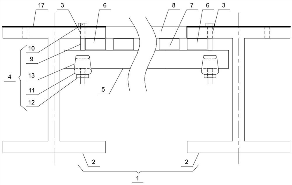
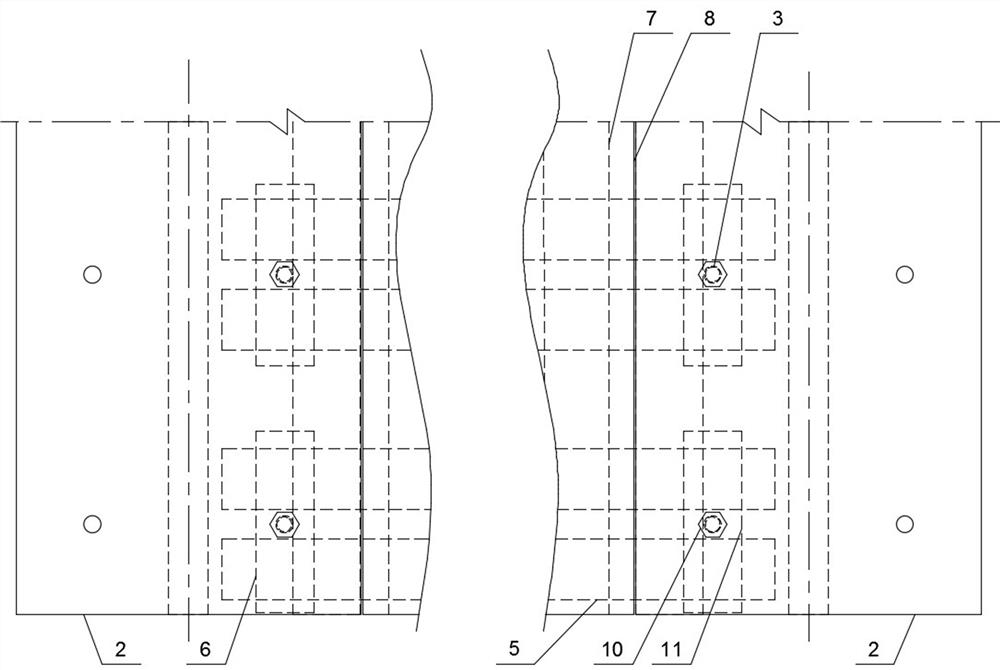
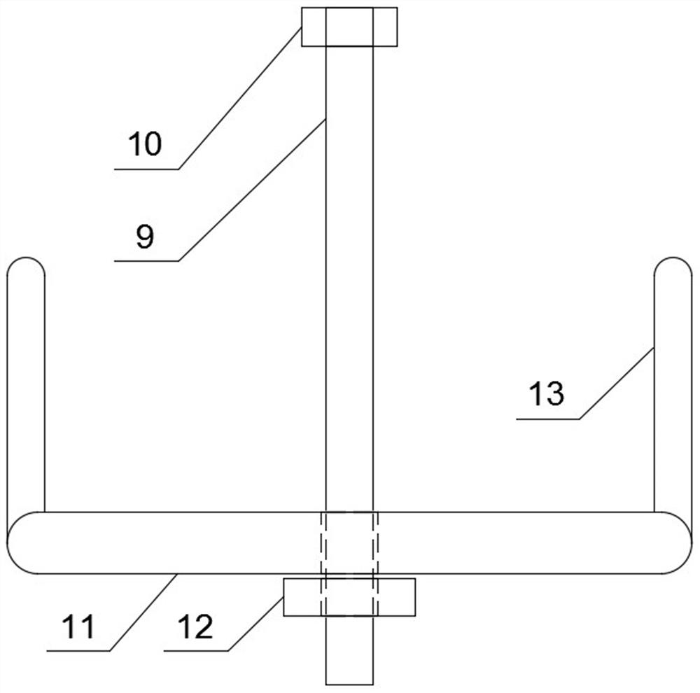
[0027] In order to make the purpose, technical solutions and advantages of the embodiments of the present invention more clear, the following will be combined with the appended Figure 1-5 , clearly and completely describe the technical solutions of the embodiments of the present invention. Apparently, the described embodiments are some, not all, embodiments of the present invention. All other embodiments obtained by those skilled in the art based on the described embodiments of the present invention belong to the protection scope of the present invention.

[0028] Such as Figure 1-5 Shown: a hanging formwork structure for a steel structure composite floor slab, including a steel structure beam, a row of first installation holes are respectively spaced on the inside of a pair of I-beams along the length direction of the steel structure beam, and each first installation hole A hanging part is installed in each of them, and the two rows of first installation holes on the insi...


PUM


Abstract

The invention provides a suspended formwork structure of a steel structure composite floor slab, and belongs to the technical field of building construction. The suspended formwork structure comprises a steel structure beam; the inner sides of a pair of I-shaped beams of the steel structure beam along the length direction are respectively provided with a row of first mounting holes at intervals; each first mounting hole is internally provided with a hanging part; the two rows of first mounting holes in the inner sides of the pair of I-shaped beams are in one-to-one correspondence; steel pipes are erected on the two hanging parts in one-to-one correspondence in the width direction of the steel structure beam; first square battens are arranged between the upper portions of the two ends of each steel pipe and the corresponding I-shaped beam in a clamped mode; second square battens are arranged on all the steel pipes in the length direction of the steel structure beam at intervals; a formwork is placed on the upper portion of the second square battens; and the upper surface of the formwork is flush with the upper surface of the steel structure beam. According to the suspended formwork structure of the steel structure composite floor slab, the structure is simple and reliable, the construction efficiency is high, the lower construction operation space is saved, interpenetration operation is facilitated, the construction period is shortened, most parts can be reused, and the cost is saved.

Description

technical field [0001] The invention relates to the technical field of building construction, in particular to a hanging formwork structure of a steel structure composite floor slab. Background technique [0002] At present, the cast-in-place floor slabs of steel structures mostly use truss floor slabs, profiled floor slabs and traditional floor supports. Among them, the full house floor support needs to be erected on the ground or the next floor. Such erection has a long construction period, a large investment in turnover materials, and a high investment cost. It can only be carried out after the support is removed, which restricts the construction of the lower layer; especially for super high formwork, there is a safety hazard of poor overall stability due to the full house support. [0003] In addition, the use of truss floor slabs or profiled floor slabs requires the use of crane equipment to assist hoisting first, which takes up the use of hoisting equipment and vertic...

Claims


Application Information

Patent Timeline
Patent Type & Authority Applications(China)
IPC IPC(8): E04G17/18E04G11/48
CPCE04G17/18E04G11/48Y02A30/60
Inventor 姜红军郑雅张小波刘小班王亚平
Owner 河南中企建筑工程有限公司
Why Eureka
Try Eureka