Spring type fiber reinforced plastic micro-expanded concrete member

A technology of micro-expansion concrete and fiber reinforcement, which is applied to building components, structural elements, building reinforcements, etc., can solve the problems of restricting the large-scale application of fiber reinforcement and low compressive strength of fiber reinforcement, so as to improve the axial bearing capacity, Effects of avoiding corrosion of steel bars and improving corrosion resistance and durability

Active Publication Date: 2017-01-18
GUANGDONG RES INST OF WATER RESOURCES & HYDROPOWER
View PDF8 Cites 0 Cited by
  • Summary
  • Abstract
  • Description
  • Claims
  • Application Information

AI Technical Summary

Problems solved by technology

However, fiber reinforcement has the problem of low compressive strength. The anisotropy of fiber reinforcement limits the large-scale application of fiber reinforcement in engineering, and the fiber reinforcement can be made into a spring type, which can convert the compressive stress of the component into the strength of the reinforcement. Tensile stress, so as to solve the problem of low compressive strength of fiber reinforcement, and promote its application in engineering

Method used


Image

  • Spring type fiber reinforced plastic micro-expanded concrete member
  • Spring type fiber reinforced plastic micro-expanded concrete member

Examples


Embodiment 1

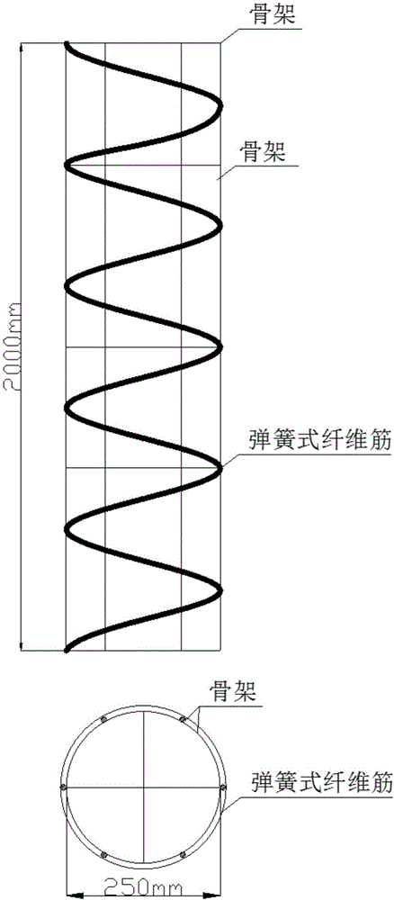
[0029] Along the longitudinal direction of the concrete column, 6 vertical bars and transverse bars at both ends and in the middle are arranged to form a skeleton, and a spring-type fiber bar is wound around the erecting bars, and the axial intercept of the spring-type fiber bar is 400mm; Before the concrete components are poured, the skeleton is placed in the mold, and the end plates connected with the hoop plates are respectively installed at both ends of the skeleton; the ready-mixed concrete material is transported into the horizontally placed mold body through a concrete mixer, and the skeleton is The cage is slightly expanded and stretched; after 1-3 days of curing, the mold can be removed. The spring-type fiber bars used are basalt fiber bars, and the concrete used is shrinkage-compensating concrete. The schematic diagram of the concrete member of this embodiment is shown in the attached figure 1 .

Embodiment 2

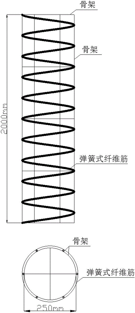
[0031] Arrange 6 vertical bars along the longitudinal direction of the concrete column and transverse bars at both ends and in the middle. The two form the skeleton. A spring-type fiber bar is wound around the erection bar. The axial intercept of the spring-type fiber bar is 200mm; Before the concrete components are poured, the skeleton is placed in the mold, and the end plates connected with the hoop plates are respectively installed at both ends of the skeleton; the ready-mixed concrete material is transported into the horizontally placed mold body through a concrete mixer, and the skeleton is The cage is slightly expanded and stretched; after 1-3 days of curing, the mold can be removed. The spring-type fiber bars used are glass fiber bars, and the concrete used is shrinkage-compensating concrete. The schematic diagram of the concrete member of this embodiment is shown in the attached figure 2 .


PUM


Abstract

The invention disclsoes a spring type fiber reinforced plastic micro-expanded concrete member. The member is composed of a main body framework and spring type fiber reinforced plastics; and the spring type fiber reinforced plastics are at a pre-stretching stress state through micro-expanded concrete. According to the member, steel bars are replaced with the fiber reinforced plastics, so that the problem that the steel bars in the concrete are rusted is radically avoided, the corrosion resistance and the durability of the concrete member are improved, and the member can be widely applied to ocean engineering and other engineering. The fiber reinforced plastics are spring-shaped, and pressing stress of the concrete member can be converted into a cooperative acting state of pressing member concrete and pulling the fiber reinforced plastics in a concrete micro-expansion manner, and the axial bearing capability of the concrete member is improved.

Description

technical field [0001] The invention relates to a spring-type fiber reinforced micro-expansion concrete component, which belongs to the field of civil engineering components. Background technique [0002] The durability of cement concrete materials has always been a major concern in the field of coastal engineering, and it is also a technical problem that needs to be solved urgently. In the process of major marine infrastructure construction, we face many challenges that are different from inland construction projects. Bearing the brunt is the seawater corrosion prevention of engineering structures, because there are corrosive ions in seawater, which reduce the alkalinity inside the concrete, and some ions will also react with the cement hydration products in the concrete, causing corrosion damage to the concrete. More importantly, the intrusion of chloride ions will destroy the passivation film of the steel bar, activate the steel bar, and eventually cause dilatant corrosi...

Claims


Application Information

Patent Timeline
IPC IPC(8): E04B1/20E04C5/07
CPCE04B1/20E04C5/07
Inventor 陈晓文李兆恒张君禄杨永民付传雄
Owner GUANGDONG RES INST OF WATER RESOURCES & HYDROPOWER
Why Eureka
Try Eureka