
Coiled material waterproof laying equipment and coiled material waterproof laying method

A coil and equipment technology, which is applied in the direction of coil coil, bridge construction, building insulation materials, etc., can solve the problems of lack of synchronous device, fold of membrane waterproof layer, slow unwinding speed, etc., and achieve the effect of ensuring smooth laying

Pending Publication Date: 2021-12-17
河南舜禹防水工程有限公司
View PDF2 Cites 3 Cited by
  • Summary
  • Abstract
  • Description
  • Claims
  • Application Information

AI Technical Summary

Problems solved by technology

First of all, in the process of laying the waterproof membrane, it is necessary to ensure that the unwinding of the coil and the recovery of the anti-adhesive release film are synchronized, otherwise the anti-adhesive release film will be broken during the recovery process due to the fast recovery speed and the slow unwinding speed, or The unwinding speed is fast and the recovery is not timely, resulting in the situation of laying the coiled material with film
However, in the above-mentioned prior art, the take-up roller and the unwinding roller lack a synchronous device, so it is impossible to realize the synchronization of the unwinding of the coil and the recovery process of the release film.
For example, in CN207727862U "a coiled material flat forming machine", it adopts the gear meshing mode to ensure that the laying roller and the protective film winding roller rotate synchronously, but because the coiled material radius on the waterproof coiled material support roll and the protection film in the construction work The radius of film winding on the film winding roller changes in real time, so the linear speed of film winding and unwinding changes in real time, so its synchronous rotation can only ensure that the angular velocity during the process of unwinding and winding is relatively constant, while The line speed cannot be guaranteed to be the same; another example is CN111717697A "an uncoiling and rewinding machine for laying waterproof coiled material", which adopts the active filming method of the filming motor
Therefore, above-mentioned prior art all can't guarantee suitable film tension, thus all can occur when film line speed is greater than coil material unwinding line speed, coil material anti-adhesive separation film will be pulled off; When the material unwinding line speed is low, the protective film of the coil will not be recovered in time, resulting in the occurrence of the "film" laying of the coil
Secondly, the unwinding rollers in the above-mentioned prior art all lack a device for providing coil unwinding tension, and cannot provide effective stretching tension for the unrolling coil, which in turn leads to wrinkles in the process of laying the waterproof layer of the coil and cannot meet the requirements of the waterproof layer. Defects in laying quality requirements
[0005] In addition, in CN111717697A "an uncoiling and rewinding machine for laying waterproof coiled material", the unwinding roller adopts the "expanding shaft" device of the mandrel tube as the positioning and locking device for the mandrel tube of the unwinding coil, because the mandrel tube expands The expansion principle of the shaft device (the expansion shaft is inserted into the mandrel tube of the coiled material, and the expansion unit of the expansion shaft expands so that the outer diameter of the expansion shaft becomes larger and then the coiled mandrel tube is tightened), which determines that the outer diameter of the expansion shaft is smaller than the mandrel tube The inner diameter of 10mm is the best. When the deviation of this size is too large, the expansion failure will occur. Therefore, the expansion shaft is used to tighten the coil mandrel tube, which will cause the "expansion shaft" to be unable to be inserted. Among the coil mandrel tubes whose appearance is deformed due to transportation and other factors, the defect that the above-mentioned deformed coil cannot be used by the equipment occurs.
There is no mandrel tube locking device on the winding rollers, and the anti-adhesive release film of the coil is directly wound on the winding roller, which makes it difficult to separate the anti-stick separation film from the winding roller, which seriously reduces the construction efficiency

Method used


Image

  • Coiled material waterproof laying equipment and coiled material waterproof laying method
  • Coiled material waterproof laying equipment and coiled material waterproof laying method
  • Coiled material waterproof laying equipment and coiled material waterproof laying method

Examples


Embodiment 1

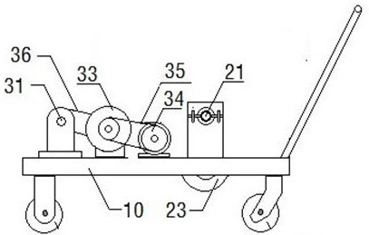
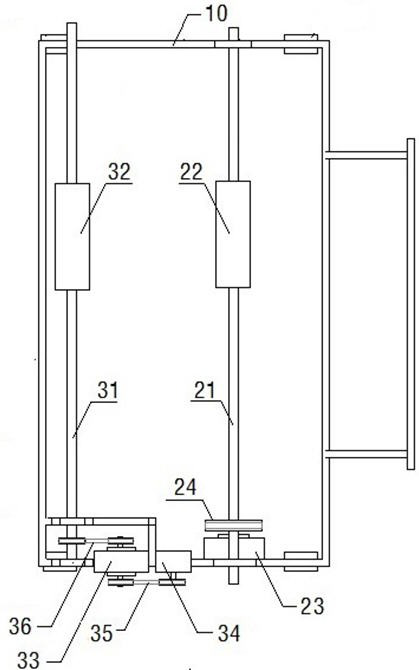
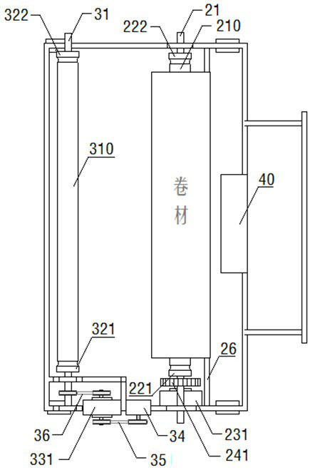
[0056] Such as Figure 4 , Figure 5 , Figure 6 As shown, this embodiment discloses a coiled material waterproof laying equipment, including equipment support 10, traveling mechanism, first semicircular bearing 201, second semicircular bearing 202, unwinding shaft 21, first coiled material mandrel tube locking chuck 221, the second coil mandrel tube locking chuck 222, the first gear 241, the second gear 242, the magnetic powder brake 231, the coil guide roller 26, the first bearing 301, the second bearing 302, the film receiving shaft 31, The first film-winding mandrel tube lock chuck 321, the second film-winding mandrel tube lock chuck 322, the magnetic powder clutch 331, the film-winding motor 34, the second transmission device 35, the third transmission device 36, the film-winding guide The roller 38 and the electric control device 40 constitute.

[0057] The running mechanism of this embodiment is made up of four wheels 11, which are installed at the four corners below...

Embodiment 2

[0082] Such as Figure 7 , Figure 8 As shown, this embodiment discloses a coiled material waterproof laying equipment, including equipment support 10, third bearing 203, fourth bearing 204, unwinding shaft 21, unrolling expansion shaft 220, unwinding expansion shaft locking knob 2201 and unwinding Mechanical torque limiter 232, the first transmission device 24, the first gear 241, the second gear 242, the coil guide roller 26, the first bearing 301, the second bearing 302, the film receiving shaft 31, the film expanding shaft 320, Film winding shaft locking knob 3201, film winding mechanical torque limiter 332, film winding motor 34, second transmission device 35, third transmission device 36, electric control device 40, meter sensor 51, meter reading display screen 52. Coil material cutting device 60, film cutting motor 61, cutting knife 62, and knife-feeding slot 63 constitute.

[0083] The third bearing 203 and the fourth bearing 204 are fixedly installed on one side of ...

Embodiment 3

[0093] Such as Figure 9 , Figure 10 , Figure 11 As shown, this embodiment discloses a coiled material waterproof laying equipment, including an equipment support 10, a traveling mechanism, a first bearing device 205, a second bearing device 206, a first unwinding shaft 211, a second unwinding shaft 212, a third roll Material mandrel tube locking chuck 223, fourth coiled material mandrel tube locking chuck 224, magnetic powder brake 231, first transmission device 24, first propulsion device 25, first nut 251, first threaded propelling rod 252 , the first handle 253, the third bearing device 303, the fourth bearing device 304, the first film receiving shaft 311, the second film receiving shaft 312, the third film receiving mandrel tube locking chuck 323, the fourth film receiving core Shaft tube locking chuck 324, magnetic powder clutch 331, film winding motor 34, second transmission device 35, third transmission device 36, second propulsion device 37, second nut 371, secon...


PUM


Abstract

The invention discloses coiled material waterproof laying equipment and a coiled material waterproof laying method, and belongs to the field of waterproof buildings. The equipment and method are used for integrated equipment operation in the waterproof construction processes such as coiled material unfolding, film collecting, laying, coiled material unfolding, film collecting and discharging, and the equipment comprises an unfolding shaft and a film collecting shaft which are rotationally connected to an equipment support. Core shaft tube locking devices are respectively mounted on the unfolding shaft and the film collecting shaft and are used for locking and fixing the coiled material and collecting the core shaft tube. An unfolding torque limiting device is used for providing tension required for unfolding the coiled material by the unfolding shaft. And a film collecting motor provides the film collecting tension required by the film collecting shaft for the recovery of a coiled material anti-sticking isolating film through the film collecting torque limitation. The equipment and method are mainly applied to spreading and laying of wet-laid or self-sticking waterproof coiled materials and discharging construction of the coiled materials.

Description

technical field [0001] The invention relates to construction equipment and a construction method in the field of building waterproofing, in particular to a coiled material waterproof layer laying equipment whose surface is covered with an anti-adhesive isolation film, and a coiled material waterproof laying method. Background technique [0002] Waterproof membrane is mainly used for the bottom of building walls, roofs, tunnels, highways, bridges and other places to resist external rainwater and groundwater leakage. It is a flexible building material product that can be rolled into rolls. The non-leakage connection material between objects is the first barrier for waterproofing of the entire project and plays a vital role in the entire project. [0003] At present, the commonly used waterproof membranes in building waterproofing include a type of waterproof membrane with a self-adhesive layer on the surface and an anti-adhesive barrier film on the "adhesive layer", such as "s...

Claims


Application Information

Patent Timeline
Patent Type & Authority Applications(China)
IPC IPC(8): B65H23/06B65H19/30B65H41/00B65H35/06B65H26/06B65H16/06B65H18/02E04D15/06E04B1/66E04G21/00E02D31/02E01D21/00E01C23/03
CPCB65H23/06B65H19/30B65H41/00B65H35/06B65H26/06B65H16/06B65H18/028E04D15/06E04B1/66E04G21/00E02D31/02E01D21/00E01C23/03
Inventor 吴敏慧魏利兰常木友
Owner 河南舜禹防水工程有限公司
Learn More