Microorganism homing type degradation device for offshore oil pollution area
A technology for offshore oil and polluted areas, which is applied in biological treatment devices, water pollutants, grease/oily substances/floating matter removal devices, etc. Degradation efficiency, the effect of improving degradation efficiency
- Summary
- Abstract
- Description
- Claims
- Application Information
AI Technical Summary
Problems solved by technology
Method used
Image
Examples
Embodiment 1
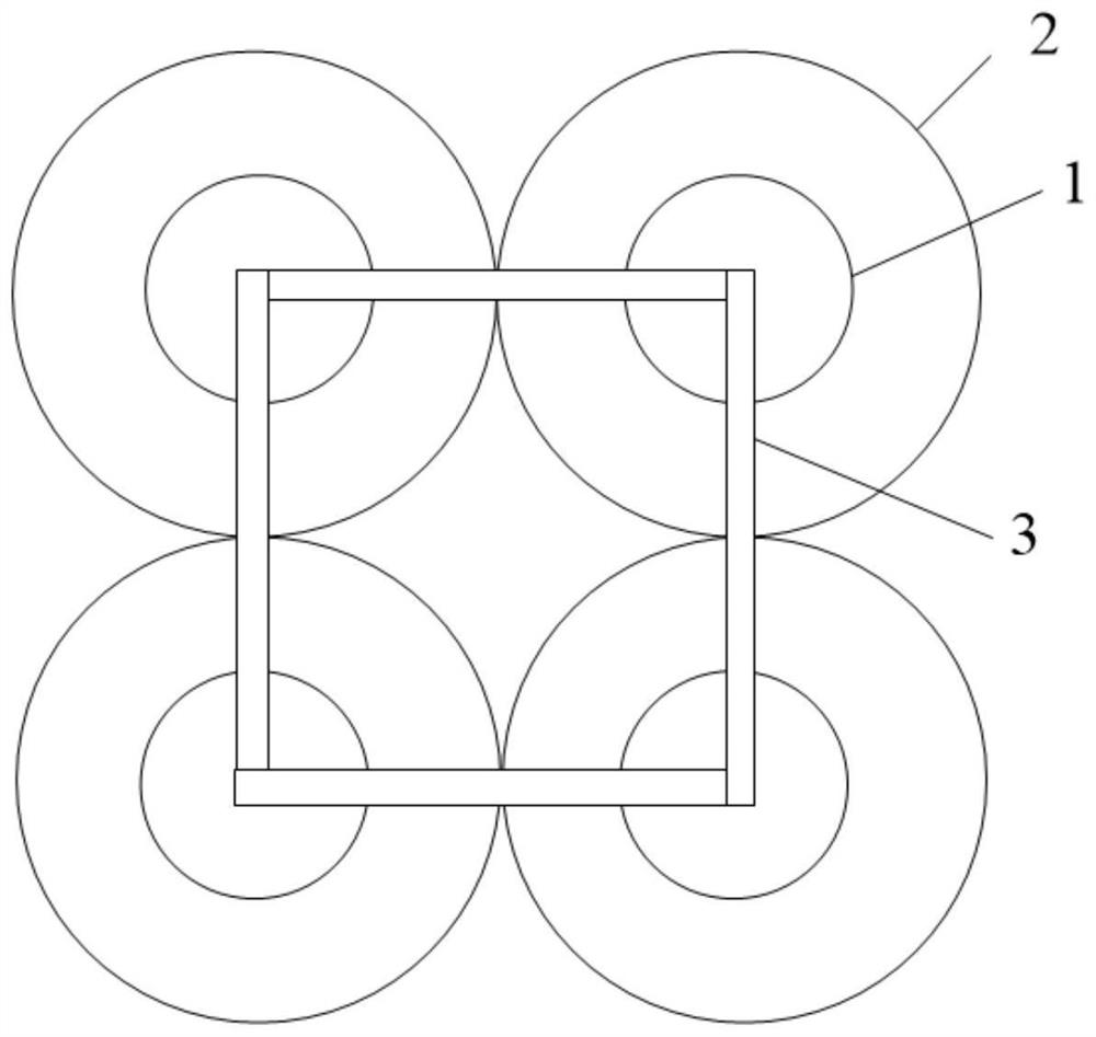
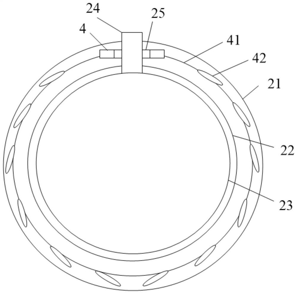
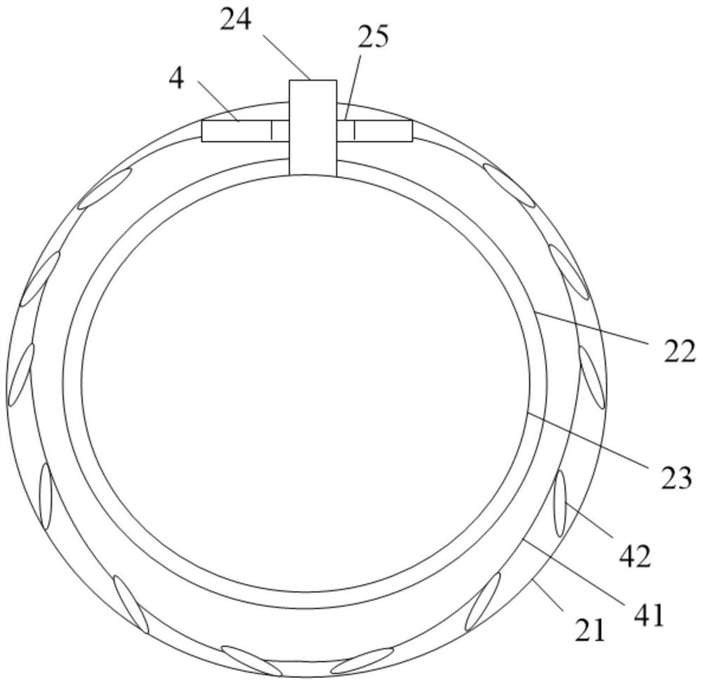
[0037] A microbial resident degradation device in marine oil polluted areas, see Figure 1-4 , including a plurality of degradation units. The degradation unit includes a floating plate 1 and a cleaning device 2. The floating plate 1 is in the shape of a cylinder or a cube, which acts as a connection and floats. The connecting pipe 3 passes between the floating plates 1 of two adjacent degradation units. Connected into a grid shape, the connecting pipe 3 can be a rigid pipe or a flexible pipe, see figure 1. The cleaning device 2 is installed below the floating tray 1, and the main purpose of the cleaning device 2 is to inhabit microorganisms capable of degrading marine oil. After connecting multiple degradation units through the connecting pipe 3, place the whole device in the seawater polluted area. Under the action of the buoyancy of the floating plate 1 and the gravity of the cleaning device 2, the floating plate 1 floats on the sea surface, which is convenient for observi...
Embodiment 2
[0048] A microorganism-inhabited degradation device in an offshore oil-polluted area, which has basically the same structure as that of Example 1, the difference is that in order to improve the degradation efficiency of microorganisms, the microorganisms that have degraded petroleum can be recuperated, and the microorganisms that have not degraded petroleum can exert their effects. In this embodiment, a circulation device with functions of microorganism supply and recovery is provided.
[0049] see Figure 5 , the circulation device includes a liquid injection ball 5 and a recovery pipe 51, the liquid injection ball 5 is located inside the sojourn ball 23, and the interior of the liquid injection ball 5 communicates with the sojourn ball 23, the top of the recovery pipe 51 is located inside the connecting pipe 24, and the bottom of the recovery pipe 51 Set through the sojourn ball 23 and communicate with the inside of the liquid injection ball 5, the top of the recovery pipe 5...
Embodiment 3
[0053] A microorganism-inhabited degradation device in an offshore oil-polluted area has basically the same structure as that of Example 2, the difference being:
[0054] see Figure 6 A plurality of floats 6 are also arranged between the oil-absorbing layer 22 and the cleaning unit, and a plurality of through grooves are opened around the surface of the oil-absorbing layer 22, and each through groove is correspondingly provided with a float 6, and each float 6 is connected with a One end of the elastic stay cord 61 and the other end of the stay cord 61 run through the inner wall of the channel of the oil-absorbing layer 22 and the sojourn ball 23, and are connected to the injection ball 5, and the stay cord 61 can move along the inner wall of the channel of the oil-absorbing layer 22 . At this time, a passage allowing the stay rope 61 to move can also be provided in the sojourn ball 23 , and the stay rope 61 is passed through the passage and then connected to the injection b...
PUM
| Property | Measurement | Unit |
|---|---|---|
| diameter | aaaaa | aaaaa |
Abstract
Description
Claims
Application Information
 - R&D
- Intellectual Property
- Life Sciences
- Materials
- Tech Scout
- Unparalleled Data Quality
- Higher Quality Content
- 60% Fewer Hallucinations
Browse by: Latest US Patents, China's latest patents, Technical Efficacy Thesaurus, Application Domain, Technology Topic, Popular Technical Reports.
© 2025 PatSnap. All rights reserved.Legal|Privacy policy|Modern Slavery Act Transparency Statement|Sitemap|About US| Contact US: help@patsnap.com


