Anti-bonding treatment method for thin oriented silicon steel
A technology of oriented silicon steel and processing methods, applied in heat treatment furnaces, heat treatment equipment, furnace types, etc., can solve problems such as the bonding of the upper and lower end surfaces of steel coils, and achieve the effect of solving bonding and good quality of the bottom layer of the edge
- Summary
- Abstract
- Description
- Claims
- Application Information
AI Technical Summary
Problems solved by technology
Method used
Image

Examples
Embodiment 1
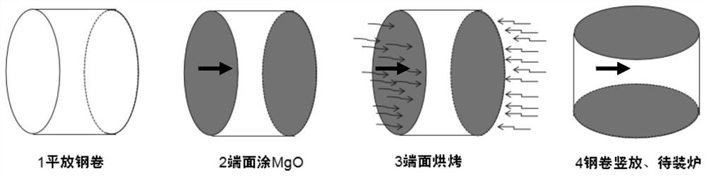
[0023] Using conventional steel, hot rolling, constituted oriented silicon steel rolled to 0.15 mm, then decarburizing annealing, figure 1 As shown, after coating MGO, the two end faces of the steel coil are perpendicular to the ground; the two end faces of the steel coil are coated with MgO (used by the MgO coating liquid for the field coating machine, which proportionally ratuous MGO: Water: TiO2 = 1: 12: 8%, MgO: Water = 1: 12, MgO: TiO2 = 1: 8%, the specific operation is: mix the MgO with water 1:12, then mix the mixture The mass of 8% of the mass of MgO is 9%, which is fully mixed. The end surface baking temperature is 120 ° C; then use the turning steel machine to place the heat-treated steel roll, load the high temperature furnace, perform high temperature annealing, an annealing temperature of 1150 ° C, and thermal tensile flat annealing; after the above steps The steel coil bonding incidence is 0%, and the underlayer of the side is 0%, whereby the bottom layer is not bond...
Embodiment 2
[0025] Using conventional steel, hot rolling, constitutive oriented silicon steel rolls to 0.18 mm, then decarburizing annealing, figure 1 As shown, after coating MGO, the two end faces of the steel coil are perpendicular to the ground; the two end faces of the steel coil are coated with MgO (used by the MgO coating liquid for the field coating machine, which proportionally ratuous MGO: TiO2 = 1: 12: 10%, MgO: Water = 1: 12, MgO: TiO2 = 1: 10%, the specific operation is: mix MGO with water at 1:12, then mix the mixture The mass of TiO2 is added to the mass of MgO mass, which is fully mixed), wherein the coating amount of each end face is 10g / m. 2 Then, the two end faces of the coated MgO are baking, and the end surface baking temperature is 140 ° C during heat treatment; and then the steel roll after the heat treatment is placed, and the high temperature furnace is applied. High temperature annealing, an annealing temperature of 1200 ° C, and heat tensile flat annealing; after t...
Embodiment 3
[0027] Using conventional steel, hot rolling, constituted oriented silicon steel rolled to 0.20 mm, then decontinum annealing, figure 1 As shown, after coating MGO, the two end faces of the steel coil are perpendicular to the ground; the two end faces of the steel coil are coated with MgO (used by the MgO coating liquid for the field coating machine, which proportionally ratuous MGO: TiO2 = 1: 6: 4%, MgO: Water = 1: 6, MgO: TiO2 = 1: 4%, the specific operation is: mix the MgO with water 1: 6 mix, then mix the mixture The mass of the mass of MgO is 4% of TiO2, which is fully mixed), wherein each end surface is 11 g / m2, and then the two end faces of the coated MgO are baking, and heat treatment The end surface baking temperature is 160 ° C; then use the turning steel machine to place the heat treated steel roll, load the high temperature furnace, perform high temperature annealing, 1250 ° C, and thermal tensile flat annealing; after the above steps The steel coil bonding incidence...
PUM
 Abstract
Description
Claims
Application Information
 - Generate Ideas
- Intellectual Property
- Life Sciences
- Materials
- Tech Scout
- Unparalleled Data Quality
- Higher Quality Content
- 60% Fewer Hallucinations
Browse by: Latest US Patents, China's latest patents, Technical Efficacy Thesaurus, Application Domain, Technology Topic, Popular Technical Reports.
© 2025 PatSnap. All rights reserved.Legal|Privacy policy|Modern Slavery Act Transparency Statement|Sitemap|About US| Contact US: help@patsnap.com