Laser radar detection system

A detection system and laser radar technology, applied in the field of laser radar detection system, can solve the problems of high production cost, complicated optical assembly and adjustment, and many devices, so as to reduce the production cost of the whole machine, compact optical path structure, and anti-light interference strong effect

Active Publication Date: 2021-12-17
上海星秒光电科技有限公司 +1
View PDF5 Cites 0 Cited by
  • Summary
  • Abstract
  • Description
  • Claims
  • Application Information

AI Technical Summary

Problems solved by technology

[0004] In order to solve the problems of the existing multi-line laser radar schemes that require more components, complex optical adjustment and high production cost of the whole machine, the purpose of the present invention is to provide a new type of laser radar detection system that can use multiple laser The transmitter and a single laser detector can also realize the detection function of multi-line laser radar, which can not only reduce the number of required components, but also greatly reduce the difficulty of optical assembly and the production cost of the whole machine, improve production efficiency, and facilitate practical application and promotion

Method used


Image

  • Laser radar detection system
  • Laser radar detection system
  • Laser radar detection system

Examples


Embodiment 1

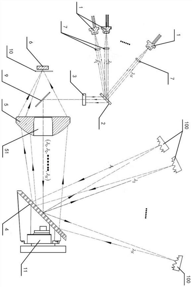
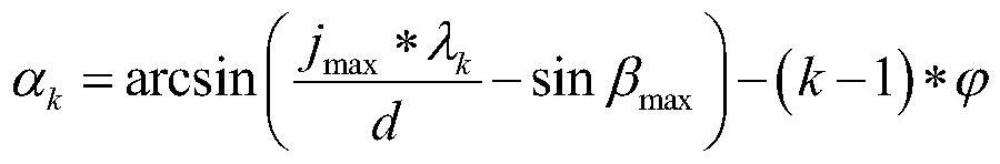
[0036] like figure 1 As shown, the lidar detection system provided in this embodiment includes a plurality of laser emitters 1, a diffraction grating 2, a cavity mirror 3, a reflective grating 4, a focusing mirror 5 and a single laser detector 6, wherein the The cavity mirror 3 has a partial reflection function; each laser emitter 1 in the plurality of laser emitters 1 is used to time-divisionally (that is, in different time slots) emit corresponding laser light through time sequence control, and make the laser light appear in The preset angular arrangement period is sorted into the diffraction grating 2 for diffraction, wherein, for each of the laser emitters 1, the grating incident angle of the corresponding laser is determined according to the following formula:

[0037]

[0038] In the formula, α k Represent the grating incidence angle corresponding to the laser of the kth laser emitter 1 in the plurality of laser emitters 1, k is a positive integer (such as figure 1 ...

Embodiment 2

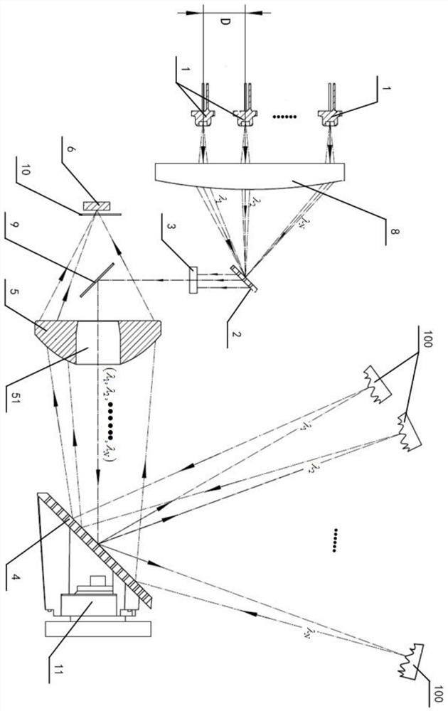
[0051] like figure 2 As shown, this embodiment also provides another optical path structure of the laser radar detection system based on the technical solution of the first embodiment, that is, the optical path structure of the laser radar detection system described in this embodiment is different from that of the first embodiment The feature is that: a beam combiner 8 is also included, wherein the beam combiner 8 has a focal plane and a focal convex surface arranged oppositely; the focal plane of the beam combiner 8 faces a row of the multiple In the laser transmitter 1, the focal convex surface of the beam combiner 8 faces the diffraction grating 2, so that the laser beams emitted by different laser transmitters 1 are collimated and incident on the diffraction grating 2 for diffraction. Each laser transmitter 1 determines the grating incident angle corresponding to the laser according to the following formula:

[0052]

[0053] In the formula, α k Indicates the grating...


PUM


Abstract

The invention relates to the technical field of laser radars, and discloses a laser radar detection system. Through the creation of the invention, a novel multi-line laser radar scheme capable of simplifying a light path structure is provided. On one hand, a diffraction grating, a cavity mirror and a reflection grating are configured in a laser light emitting light path in sequence so that lasers with different wavelengths can be emitted by a plurality of laser emitters in a time division manner, and a purpose of emitting multi-line laser to irradiate an external object is realized; on the other hand, the reflection grating and the focus lens are configured in a laser sequential reflection light path so that the retroreflection laser with different wavelengths can be focused on the same laser detector, and further, a plurality of laser emitters and a single laser detector can be utilized to realize the detection function of the multi-line laser radar can be realized. The number of required devices can be reduced, the optical adjustment difficulty and the production cost of the whole machine can be greatly reduced, and the production efficiency is improved.

Description

technical field [0001] The invention belongs to the technical field of laser radar, and in particular relates to a laser radar detection system. Background technique [0002] Lidar is a radar system that emits laser beams to detect characteristic quantities such as distance, position, and speed of target objects. Because of its excellent characteristics, lidar ranging plays an indispensable role in the perception link in the field of intelligent sports. Since multi-line lidar can provide real-time three-dimensional environmental information, it can better assist smart devices to make accurate judgments in the perception process. [0003] The existing mainstream multi-line lidar mostly adopts a mechanical rotary structure, that is, the measurement is performed in a one-to-one correspondence between the transmitter and the receiver, and the motor is used to drive the entire optical system to rotate to measure three-dimensional environmental information. However, this existin...

Claims


Application Information

Patent Timeline
Patent Type & Authority Applications(China)
IPC IPC(8): G01S17/02G01S7/481
CPCG01S17/02G01S7/481
Inventor 肖岗肖伟张帅陈杰
Owner 上海星秒光电科技有限公司
Why Eureka
Try Eureka