Protective member and communication terminal device including same
A technology for protecting components and communication terminals, which is applied in telephone communications, branch equipment, and interference protection. Effects of Propagation Loss
- Summary
- Abstract
- Description
- Claims
- Application Information
AI Technical Summary
Problems solved by technology
Method used
Image

Examples
no. 2 Embodiment approach
[0072] In addition, in the case of the protection member 100 of the above-mentioned first embodiment, the hole 11 penetrating the front and back of the first base material is formed in the first base material 10, and the second base material 20 is fitted into the hole 11, but the second base material 20 is 2. The form in which the base material 20 is attached to the first base material 10 is not limited to fitting with the holes 11 penetrating the front and back of the first base material.
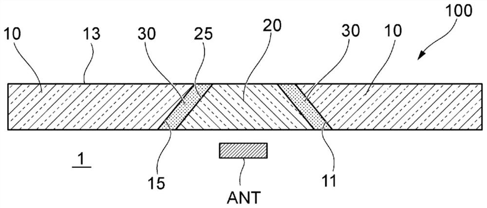
[0073] Figure 8 It is a cross-sectional view of the protective member 100 in which the second base material 20 is fitted into the hole (recess) 17 formed in the first base material 10 and recessed in the thickness direction of the first base material. Figure 9 is a cross-sectional view of the protective member, showing the arrangement of the antenna ANT with respect to the protective member 100, in which the second base material 20 is embedded in the first base material 10 formed on the ...
no. 3 Embodiment approach
[0077] Figure 10A and Figure 10B It is a schematic front view of a modified example, showing another arrangement example in which the second base material 20 is arranged on the protective member. in addition, Figure 10A and Figure 10B The illustrated shape (aspect ratio, etc.) of the protective member 100 is schematically illustrated.
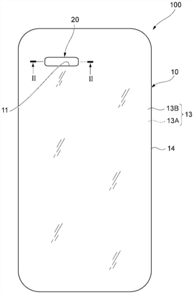
[0078] Such as Figure 10A As shown, for example, when the protection member 100 is provided on the side (front side) of the protected object 1 where the display portion is disposed, the second base material 20 may be disposed in the non-display area 5 avoiding the display portion 3 . The non-display region 5 is an opaque region in which a printed layer or the like is formed on the protective member 100 . By adding a printed layer or the like to the second base material 20 and arranging it in the non-display area 5 , the second base material 20 is intentionally arranged to be conspicuous.
[0079] Additionally, if Figure 10B As show...
no. 4 Embodiment approach
[0081] [Fourth Embodiment] (Height difference between the first base material and the second base material)
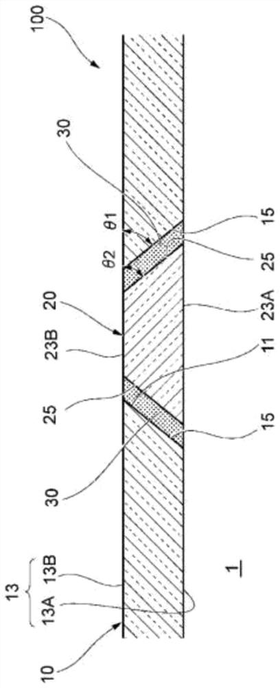
[0082] As above figure 2 As shown, in the case where the protective member 100 is provided to cover the display portion on the front side of the object 1 to be protected, the thickness between the outer surface 13B of the first base material 10 and the outer surface 23B of the second base material 20 is The height difference in the direction is preferably 10 μm or less, more preferably 3 μm or less, and still more preferably 1 μm or less. In order to reduce the level difference, the surface may be polished to be flat after bonding the first base material 10 and the second base material 20 .
[0083] In this way, the visibility of the display unit does not decrease. In addition, the height difference is small, and the tactility and operability of the touch panel are not impaired.
[0084] On the other hand, when the protection member 100 covers the back side of the ...
PUM
| Property | Measurement | Unit |
|---|---|---|
| thickness | aaaaa | aaaaa |
| depth | aaaaa | aaaaa |
| thickness | aaaaa | aaaaa |
Abstract
Description
Claims
Application Information
 - R&D
- Intellectual Property
- Life Sciences
- Materials
- Tech Scout
- Unparalleled Data Quality
- Higher Quality Content
- 60% Fewer Hallucinations
Browse by: Latest US Patents, China's latest patents, Technical Efficacy Thesaurus, Application Domain, Technology Topic, Popular Technical Reports.
© 2025 PatSnap. All rights reserved.Legal|Privacy policy|Modern Slavery Act Transparency Statement|Sitemap|About US| Contact US: help@patsnap.com