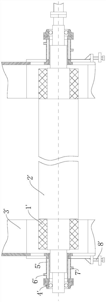
[0003] refer to figure 1 , in the prior art, the graphite retaining ring 1' is installed at the end of the transition roller 2' and is located in the sealing box 3', which can block the 600° high temperature from the sealing box 3', but the graphite retaining ring 1' is placed The position is not completely sealed, and a cavity will be formed between the end of the transition roller 2', the graphite retaining ring 1' and the end of the sealing box 3', and the heat
convection generated in the cavity will cause heat loss, and the cavity The heat
convection generated is not conducive to the temperature regulation in the sealed box 3', and the uneven temperature field in the sealed box 3' will affect the quality of the glass; and the cavity will conduct the high temperature in the sealed box 3' to the
spherical bearing seat 4', thereby causing damage to the
spherical bearing seat 4'; therefore, a bearing plate 5' is installed between the seal box 3' and the
spherical bearing seat 4' and on the transition roller 2', and the bearing plate 5' is set on the bearing plate 5' The water outlet 6' and the water outlet 7', the water in the bearing plate 5' is used to cool the spherical bearing seat 4';
[0004] However, at this time, the temperature inside the bearing plate 5' is low, and the
temperature difference between the position where the bearing plate 5' is installed on the sealing box 3' and other positions is relatively large, resulting in the deformation of the end of the sealing box 3', and the spherical bearing seat 4' and the transition roller 2' The original installation angle is destroyed, which makes it easy to damage the spherical bearing seat 4' and block the transition roller 2', resulting in production accidents; at the same time, the deformation of the bearing plate 5' leads to gaps around it, which are usually filled with sealing mud for the insulation effect , the bolts on the bearing plate 5' are often sealed with sealing mud, so the sealing mud needs to be removed every time adjustment is made, which is inconvenient to operate; in addition, there are water inlet and outlet pipes on the bearing plate 5', which require process
piping and It is matched, resulting in the staggered external pipelines of the sealed box 3', which is not beautiful, and the
water flow also causes a waste of
water resources, which is not economical and
environmentally friendly;
[0005] Due to the high
internal temperature of the sealing box 3', the transition roller 2' will move laterally after being heated and expanded. In the prior art, the two ends of the transition roller 2' table are the moving end and the other end is the fixed end; The top wire on the '' locks the transition roller 2' to prevent it from moving, and the transition roller 2' at the fixed end rotates through the
flange connection to the gearbox; the transition roller 2' at the moving end can pass through the spherical bearing seat 4' after being heated and expanded Move laterally outward, at this time, the spherical bearing seat 4' has to bear the thrust of the expansion of the transition roller 2', which is easy to cause damage to the bearing;
[0006] The top wire 8' is installed under the bearing plate 5', and the top wire 8' is used to fine-tune the height of the transition roller 2'; due to the high external temperature of the sealing box 3', the temperature of the bearing plate 5' installed on it is also high, Therefore, it is not easy to precisely fine-tune the height of the transition roller 2' through the top wire 8' connected to the bearing plate 5'
[0007] The publication number is CN2632086Y, which discloses a sealing device for the shaft head of the transition roller table. This patent still uses a graphite ring hard seal, but there is a gap in the hard seal in
actual use; if the gap is small, then when the structure is heated and deformed (The temperature of the body at this place will rise above 300 degrees), the roller will be locked, and a major accident will occur; if the gap is large, an
airflow channel will be formed, and a large pressure relief will be unfavorable for maintaining the
internal pressure of the
tin bath. Affect the quality of the glass; in addition, no matter how large or small the gap is, as long as there is a gap, the gap will conduct high temperature to the outside of the sealed box, thereby affecting the bearing housing

