Plate type viscous damper, tuned mass damper and damper coefficient adjusting method
A viscous damper and damper technology, applied in protective buildings/shelters, building components, building structures, etc., can solve the problems of high cost and insufficient life of dampers, and achieve low cost, simple structure, The effect of simple installation structure
- Summary
- Abstract
- Description
- Claims
- Application Information
AI Technical Summary
Problems solved by technology
Method used
Image
Examples
Embodiment 1
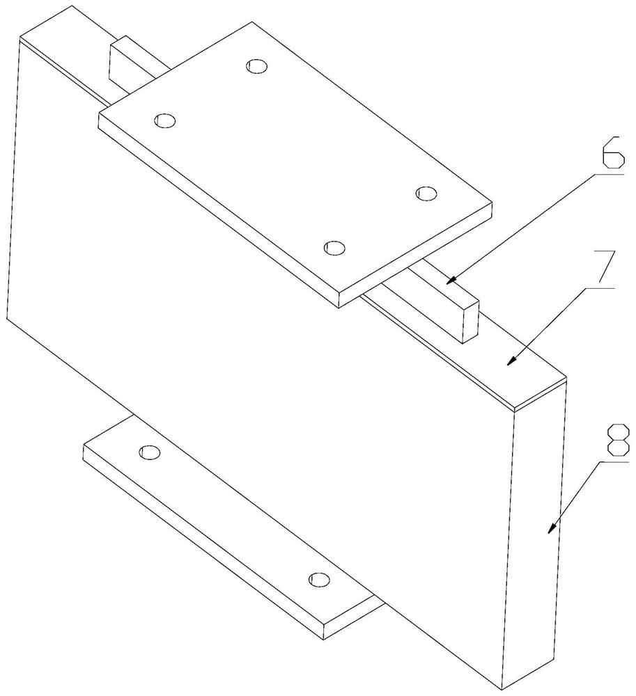
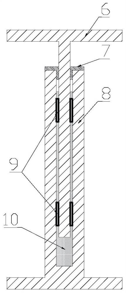
[0031] Embodiment 1: as figure 1 and 3 As shown, a plate-type viscous damper 2 includes: an upper shear plate 6, a lower cavity 8 plates, a limit buckle assembly 9, and a flexible dustproof cover 7. The structure is simple, no pressure seal is required, and the working life is long. The shearing plate 6 is inserted into the lower cavity 8 with gaps; the upper shearing plate 6 is symmetrically opened with limiting holes on the plate surface, and the limiting buckle assembly 9 is fastened on the limiting hole, and the upper shearing plate 6 is inserted into the lower cavity. When the cavity is 8, the two ends of the limit buckle assembly 9 are matched with the inner wall surface of the lower cavity 8 with a small gap; During movement, the limit buckle assembly 9 ensures that the gap between the two fluctuates in a small range; the surroundings and the bottom surface of the lower cavity 8 are closed, and the top surface is open, without pressure sealing; the damping fluid filled...
Embodiment 2
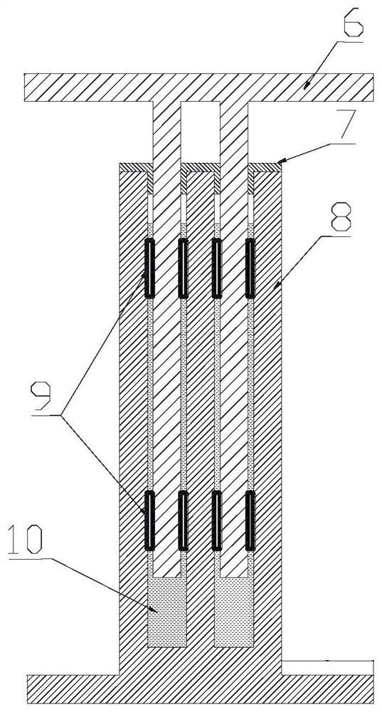
[0033] Embodiment 2: as image 3 and 4 As shown, this embodiment is an improvement on Implementation 1; the wall of the upper shear plate 6 of the plate-type viscous damper 2 and the corresponding shear cavity of the lower cavity 8 can form a multi-cavity structure, and the multi-cavity parallel connection can be obtained from the structure and damping output optimization design. In other embodiments, an insert plate may also be added in the lower cavity 8, or ribs vertical to the plate surface may be added on the plate surface to form a multi-cavity structure.
Embodiment 3
[0034] Embodiment 3: on the basis of embodiment 1 or 2, as Figure 7 , 8 As shown, a mounting plate 15 is connected to the top of the upper shearing plate, and several waist-shaped holes 14 are provided on the mounting plate 15. When the upper shearing plate 6 is installed and fixed, it can be installed and fixed with the upper connecting plate 1 through the waist-shaped holes. , and the distance between the upper shear plate 6 and the inner wall of the lower cavity 8 can be adjusted through the waist hole 14 . Then change the damping coefficient to meet the shock absorption requirements of different building structures.
PUM
 Abstract
Description
Claims
Application Information
 - R&D
- Intellectual Property
- Life Sciences
- Materials
- Tech Scout
- Unparalleled Data Quality
- Higher Quality Content
- 60% Fewer Hallucinations
Browse by: Latest US Patents, China's latest patents, Technical Efficacy Thesaurus, Application Domain, Technology Topic, Popular Technical Reports.
© 2025 PatSnap. All rights reserved.Legal|Privacy policy|Modern Slavery Act Transparency Statement|Sitemap|About US| Contact US: help@patsnap.com


