
Continuous separation device for micro-plastics with different densities and application of continuous separation device

A separation device and microplastic technology, which is applied in measurement devices, material analysis by optical means, and material analysis, etc., can solve the problems of low precision, low overall efficiency, and inability to accurately determine the type of microplastics, and achieve accurate separation, The effect of avoiding loss and residue and shortening manual operation time

Active Publication Date: 2021-12-24
INNER MONGOLIA AGRICULTURAL UNIVERSITY
View PDF4 Cites 0 Cited by
  • Summary
  • Abstract
  • Description
  • Claims
  • Application Information

AI Technical Summary

Problems solved by technology

However, the existing microplastic density separation method can only identify microplastics in one density range (such as less than 1.2g / cm3) at a time. 3 or less than 1.4g / cm 3 ), which may contain a variety of microplastics, the accuracy is not high, and the overall efficiency is also low, so it is impossible to accurately determine the type of microplastics

Method used


Image

  • Continuous separation device for micro-plastics with different densities and application of continuous separation device
  • Continuous separation device for micro-plastics with different densities and application of continuous separation device
  • Continuous separation device for micro-plastics with different densities and application of continuous separation device

Examples


experiment example

[0085] In order to verify the separation effect of the continuous separation device of microplastics of different densities provided by the present invention, we first select four kinds of microplastics of known composition (detected by Fourier transform infrared spectroscopy), which are artificial fibers (1.48g / cm 3 ), polyester (density 1.38g / cm 3 ), polystyrene (1.05g / cm 3 ) and polyethylene (0.96g / cm 3 ), 20 pieces each, the size is 0.5mm-5mm, and the shape is fibers, fragments and films. Mix all four kinds of microplastics into 1L of distilled water as the water sample to be tested.

[0086] Then configure solutions with different densities: the density is 1.0g / cm 3 of distilled water (referred to as X1 solution), the density is 1.2g / cm 3 Saturated sodium chloride solution (denoted as X2 solution), density is 1.3g / cm 3 Potassium formate solution (denoted as X3 solution), density is 1.4g / cm 3 Potassium formate solution (referred to as X4 solution). Next, the continu...


PUM

PropertyMeasurementUnit
densityaaaaaaaaaa
densityaaaaaaaaaa
densityaaaaaaaaaa

Abstract

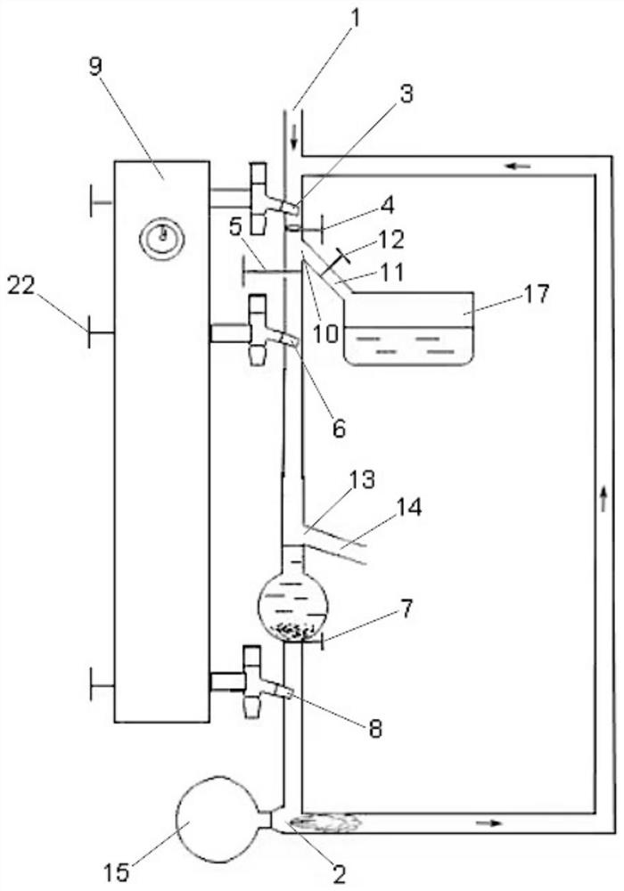
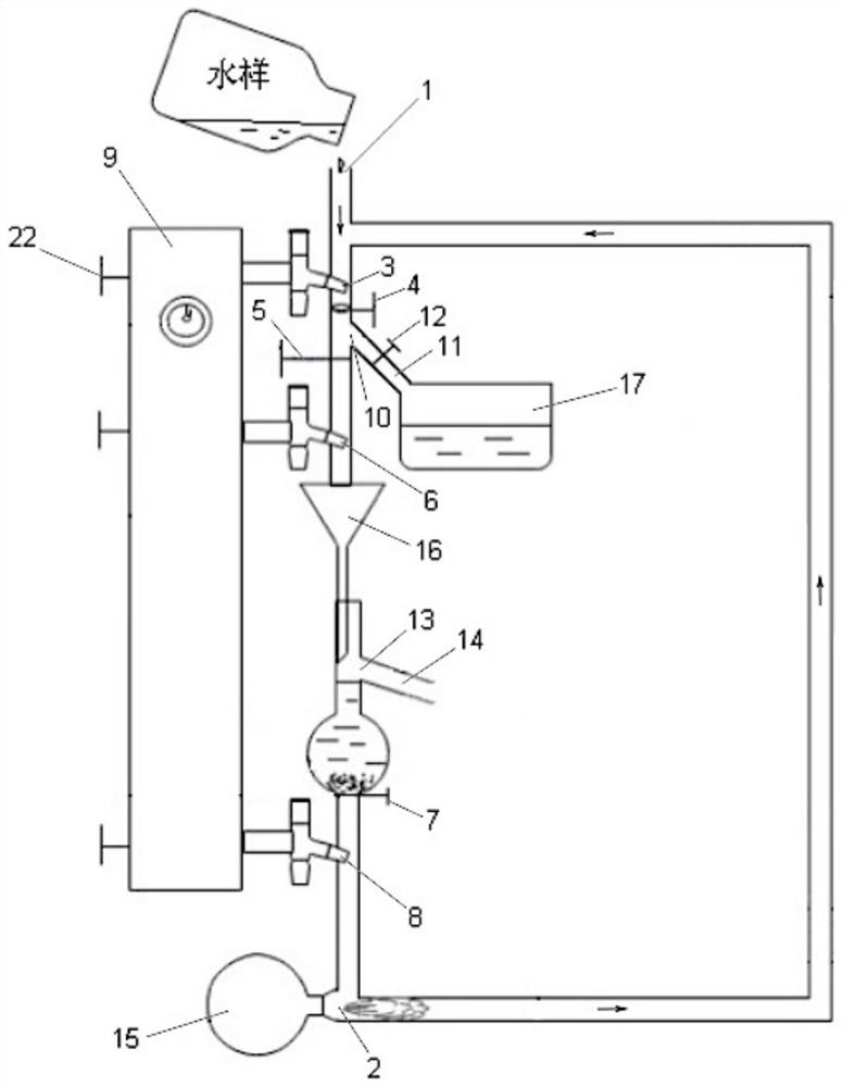
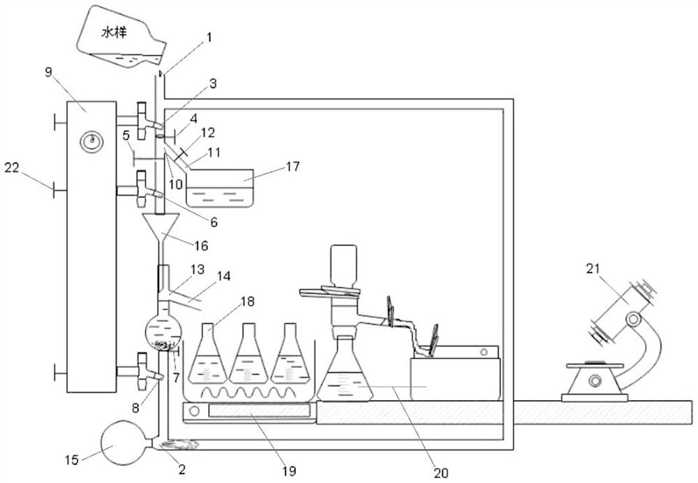
The invention relates to the field of water environment protection, in particular to a continuous separation device for micro-plastics with different densities and application of the continuous separation device. The device comprises a separation pipeline and a return pipeline. The upper end of the separation pipeline is provided with a sample inlet, and the lower end is provided with a high-pressure gas inlet; a first rotary spray head, a turnover screen, a first valve, a second rotary spray head, a second valve and a third rotary spray head are sequentially arranged in a pipeline between the sample inlet and the high-pressure gas inlet from top to bottom; the rotary nozzle is externally connected with a high-pressure fluid infusion flusher; a waste liquid pipe is arranged on the pipeline between the turnover screen and the first valve, and a third valve is arranged in the waste liquid pipe; an overflow pipe is arranged on the pipeline between the second rotary spray head and the second valve; an opening in the upper end of the return pipeline is formed in a pipeline between the sample inlet and the first rotary spray head; the lower end of the return pipeline is communicated with the lower end of the separation pipeline; the high-pressure gas inlet faces the backflow pipeline and is externally connected with a high-pressure gas pump. The device can efficiently and accurately separate micro-plastics with different densities in a water sample.

Description

technical field [0001] The invention relates to the field of water environment protection, in particular to a continuous separation device for microplastics with different densities and its application. Background technique [0002] Plastic has the characteristics of low price, no rust, no perishability, low quality, good insulation, etc., and is widely used in all aspects of human life. According to statistics, the total production of plastics in the world reached 348 million tons in 2017 alone, and it is estimated that by 2050, plastic products will increase by 33 billion tons. However, only a small part of waste plastic can be recycled or incinerated, and most of it is buried in landfill or accumulated in the natural environment. The degradation of waste plastics in the environment is extremely slow, but under some physical and chemical effects, large pieces of garbage can form plastic debris, and when the diameter of the debris is less than 5mm, it can be defined as Mic...

Claims


Application Information

Patent Timeline
Patent Type & Authority Applications(China)
IPC IPC(8): G01N1/34G01N1/40G01N15/10G01N21/3563
CPCG01N1/34G01N1/4077G01N15/10G01N21/3563G01N2001/4088G01N2021/3595G01N2015/1024Y02W30/62
Inventor 刘禹
Owner INNER MONGOLIA AGRICULTURAL UNIVERSITY
Learn More