Tightly Coupled Phased Array Antenna Based on Lumped Element Matching Network

A phased array antenna and matching network technology, applied in the field of communication, can solve the problems of complex structure of the feeder network, affecting the radiation performance, unfavorable design and installation, etc., achieving the effect of wide application range, extremely low profile, and overcoming errors that are prone to occur.

Active Publication Date: 2022-07-22
XIDIAN UNIV
View PDF2 Cites 0 Cited by
  • Summary
  • Abstract
  • Description
  • Claims
  • Application Information

AI Technical Summary

Problems solved by technology

[0006] The purpose of the present invention is to address the deficiencies in the prior art, and propose a tightly coupled phased array antenna based on lumped elements to form a matching network, aiming to solve the problem that the array profile is too high when the antenna works at low frequencies, and the antenna is in the scanning process. Too high middle and secondary lobes affect radiation performance, and the complex structure of the feed network is not conducive to design and installation
The present invention utilizes multi-section lumped element cascading to form a matching network, and through multi-section lumping element cascading, the total reflection coefficient of the matching network can be approximated as a decreasing smooth function, so that energy reflection caused by impedance mismatch can be continuously slowed down , so as to solve the problem that the high antenna sidelobe affects the antenna performance during the scanning process
In the matching network adopted in the present invention, seven dielectric plate units arranged in one dimension and the capacitance and inductance attached to the surface of the dielectric plate unit are welded into a whole. When assembling, it is only necessary to embed the positive radiation patch and the dielectric substrate as a whole. In the drilling hole in the center, so as to solve the problem that the feed structure of the prior art is too complicated and unfavorable for installation

Method used


Image

  • Tightly Coupled Phased Array Antenna Based on Lumped Element Matching Network
  • Tightly Coupled Phased Array Antenna Based on Lumped Element Matching Network
  • Tightly Coupled Phased Array Antenna Based on Lumped Element Matching Network

Examples


Embodiment Construction

[0018] The present invention will be described in further detail below with reference to the accompanying drawings and embodiments.

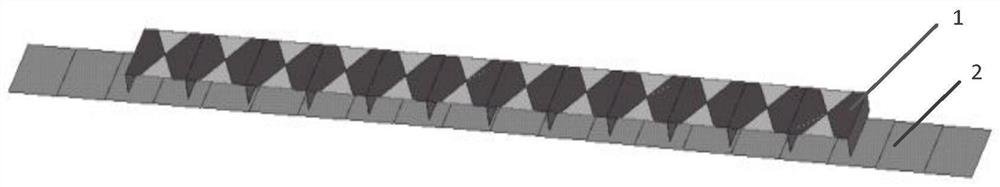
[0019] refer to figure 1 , the antenna array structure of the present invention will be further described in detail.

[0020] The antenna array of the present invention includes an antenna array element 1 and a reflector 2 . The tightly coupled phased array antennas are arranged in sequence along the negative direction of the Z axis, and the number along the X and Y axes is composed of M and N antenna elements and reflector 2 respectively, where M and N are both positive integers greater than or equal to 1. The reflector 2 is placed below the array element at a quarter of the wavelength of the center frequency.

[0021] In the embodiment of the present invention, M=12 and N=12.

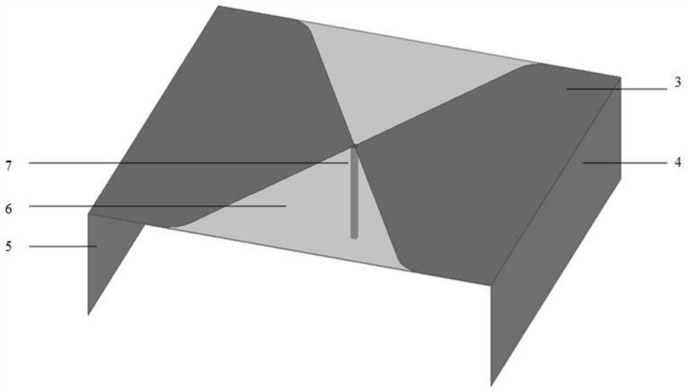
[0022] refer to figure 2 , the structure of the antenna array element in the present invention is further described in detail.

[0023] The antenna array element ...


PUM


Abstract

The invention discloses a tightly coupled phased array antenna based on lumped elements to form a matching network, comprising an antenna array element and a reflector. The matching network below the radiating patch. The matching network is a whole composed of seven dielectric plate units arranged one-dimensionally along the Z axis, and twenty capacitors and inductance weldings attached to the surface of the dielectric plate unit. The tightly coupled phased array antenna is composed of M×N antenna elements and reflectors arranged in sequence along the negative direction of the Z axis along the X and Y axes, where M and N are both positive integers greater than or equal to 1. The invention solves the problems that the prior art antenna array has a high profile and the feeding structure is too complicated, which leads to errors in the installation process.

Description

technical field [0001] The invention belongs to the field of communication technology, and further relates to a tightly coupled phased array antenna based on a lumped feeding network in the field of electromagnetic field and microwave technology. The invention can be used in the microwave band, and can realize the scanning angle and side lobe level required for space detection and information countermeasure under the condition of satisfying the working frequency band and low profile required by the antenna, and is suitable for the space detection and information of various aircraft carrier platforms Against apps. Background technique [0002] The tightly coupled phased array antenna is mainly closely related to the radar's ability to complete many new tasks in the case of multiple targets and multi-functions, and the ability to perform high-resolution one-dimensional imaging and two-dimensional imaging of multiple targets, and its cross-section is small and low. The advanta...

Claims


Application Information

Patent Timeline
Patent Type & Authority Patents(China)
IPC IPC(8): H01Q21/06H01Q21/00H01Q3/30H01Q1/28H01Q1/50
CPCH01Q21/065H01Q21/0006H01Q3/30H01Q1/28H01Q1/285
Inventor 翁子彬李雨桐孙鸽张立赵钢焦永昌
Owner XIDIAN UNIV
Why Eureka
Try Eureka