Rapid cutting device for copper bar

A fast cutting, copper bar technology, applied in shearing devices, accessories of shearing machines, maintenance and safety accessories, etc., can solve the problems of waste of resources, reduce the quality of copper bars, uneven cutting surface, etc., to reduce waste , Improve the effect of cutting quality

Pending Publication Date: 2021-12-28
红旗集团江西铜业有限公司
View PDF12 Cites 0 Cited by
  • Summary
  • Abstract
  • Description
  • Claims
  • Application Information

AI Technical Summary

Problems solved by technology

[0004] The purpose of the present invention is: in order to solve the problem that when the rapid cutting device for copper rods is in use, because copper is a relatively precious metal, it will cause waste when cutting, and the flying waste will lead to waste of resources. At the same time, the hardness of copper rods is not high. When cutting, copper The rod is easily deformed, which leads to uneven cutting surface and reduces the quality of the copper rod after cutting. A fast cutting device for copper rods is provided.

Method used


Image

  • Rapid cutting device for copper bar
  • Rapid cutting device for copper bar
  • Rapid cutting device for copper bar

Examples


Embodiment 1

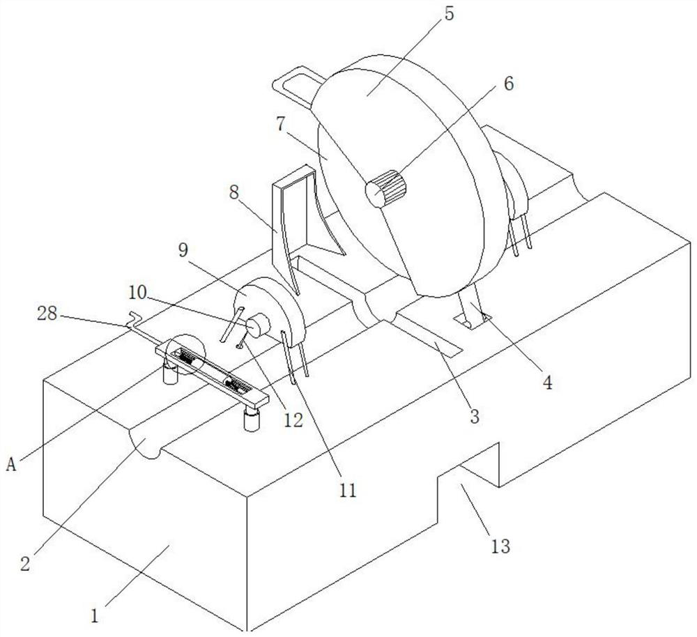
[0030] A rapid cutting device for copper and copper rods, comprising a main body 1, the top of the main body 1 is connected with a connecting column 4 through a spring 16, and a protective frame 5 is fixed on one side of the connecting column 4, and the middle position of one side of the protective frame 5 is A rotating motor 6 is installed at the position, and the output end of the rotating motor 6 is connected with a cutting knife 7, and a feeding groove 2 is arranged at the middle position of the top of the main body 1, and a cutting groove 3 is arranged at the middle position of the feeding groove 2.

[0031] The connecting column 4 cooperates with the spring 16 to facilitate the reset of the protective frame 5, thereby facilitating the operation of the operator and preventing the cutting knife 7 from falling due to gravity. 3. It is convenient for the cutting knife 7 to enter, so as to complete the purpose of cutting.

Embodiment 2

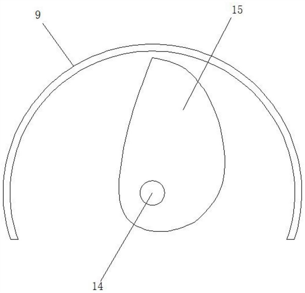
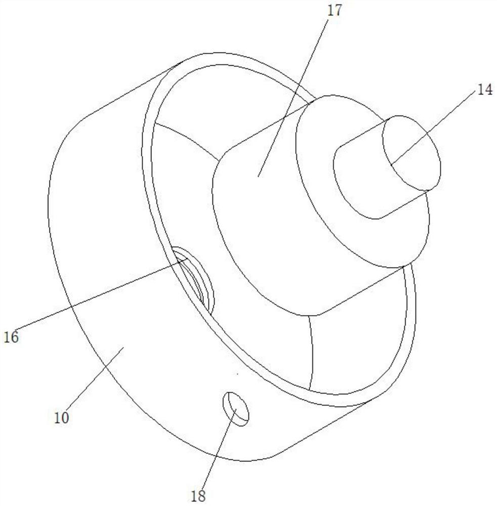
[0033] Both ends of the top of the main body 1 are equipped with a limit mechanism through the mounting bracket 11, and the top of the main body 1 is provided with an auxiliary plate 8 at one end of the cutting groove 3, and slots 20 are provided on both sides of the rear surface of the main body 1, and the slots 20 Both ends of the interior are provided with a first chute 21, one side of the first chute 21 is provided with a second chute 22, the inside of the slot 20 is slidably connected with a pull column 19, and both ends of the pull column 19 are A slide block 23 cooperating with the first chute 21 and the second chute 22 is provided, the limit mechanism includes a limit frame 9, and one side of the limit frame 9 is fixed with a tightening frame 10, and the limit frame 9 The inner rotation is connected with a rotating shaft 14 that penetrates to the inside of the tightening frame 10. The outer side of the rotating shaft 14 is positioned at the inside of the limiting frame ...

Embodiment 3

[0036] One side of the pull column 19 is provided with a handle, and the middle position on the other side of the pull column 19 is connected with the end of the rope 12, the rope 12 penetrates to the inside of the main body 1, and the inner top of the slot 20 is provided with a handle connected with the rope 12. Matching wheel.

[0037] The handle provided is convenient for the pulling of pull column 19, and pull column 19 is connected with rope 12, is convenient to the transmission of rope 12, and the running wheel of setting, avoids the wear and tear of rope 12 inside main body 1, increases the service life of rope 12.


PUM


Abstract

The invention discloses a rapid cutting device for a copper bar, and relates to the field of copper bar cutting. The rapid cutting device comprises a body, the top of the body is rotatably connected with a connecting column through a spring, one side of the connecting column is fixedly provided with a protective frame, the middle position of one side of the protective frame is provided with a rotating motor, and the output end of the rotating motor is connected with a cutting knife; and a feeding groove is formed in the middle position of the top of the body. Arranged pull columns are pulled towards one side, the pull columns are rotated to enable sliding blocks to enter second sliding grooves, then limiting of the pull columns is completed, meanwhile, the pull columns drive ropes to pull, the ropes drive rotating rollers to rotate, the rotating rollers drive limiting plates to rotate, the limiting plates rotate to fix the copper rod in the feeding groove, and the steps are repeated; and the steps are repeated on the other set of limiting plate, so that the two ends of the copper bar at the cutting position are fixed, the phenomenon that cutting is uneven due to displacement of the copper bar during cutting is avoided, and then the cutting quality is improved.

Description

technical field [0001] The invention relates to the field of copper rod cutting, in particular to a rapid cutting device for copper rods. Background technique [0002] Copper is a metal element and a transition element. Its chemical symbol is Cu, English copper, and its atomic number is 29. Pure copper is a soft metal. Good, high thermal conductivity and electrical conductivity, so it is the most commonly used material in cables and electrical and electronic components. It can also be used as a building material and can be composed of many kinds of alloys. Copper alloys have excellent mechanical properties and low resistivity. The most important For the number of bronze and brass, many machinery factories will buy semi-finished copper, of which copper rods are essential, but when copper rods are used, they need to be cut to meet the use of copper rods. [0003] When the current rapid cutting device for copper rods is in use, because copper is a relatively precious metal, it...

Claims


Application Information

Patent Timeline
Patent Type & Authority Applications(China)
IPC IPC(8): B23D19/00B23D33/04B23Q11/06B23Q11/08B23Q11/00
CPCB23D19/00B23D33/04B23Q11/06B23Q11/08B23Q11/0042
Inventor 王星余王贤培蒋冰锋
Owner 红旗集团江西铜业有限公司
Why Eureka
Try Eureka