Cooling liquid recycling mechanism for numerical control machine tool
A technology for CNC machine tools and recycling mechanisms, which is applied in metal processing machinery parts, maintenance and safety accessories, metal processing equipment, etc.
- Summary
- Abstract
- Description
- Claims
- Application Information
AI Technical Summary
Problems solved by technology
Method used
Image

Examples
Embodiment 1
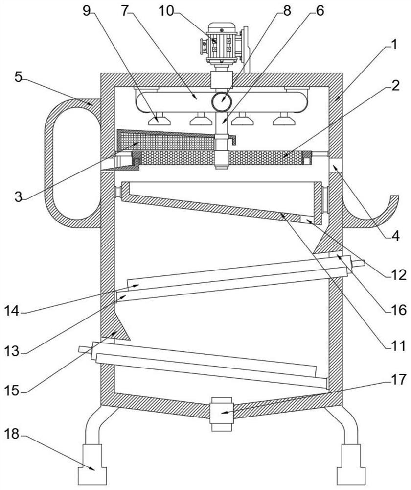
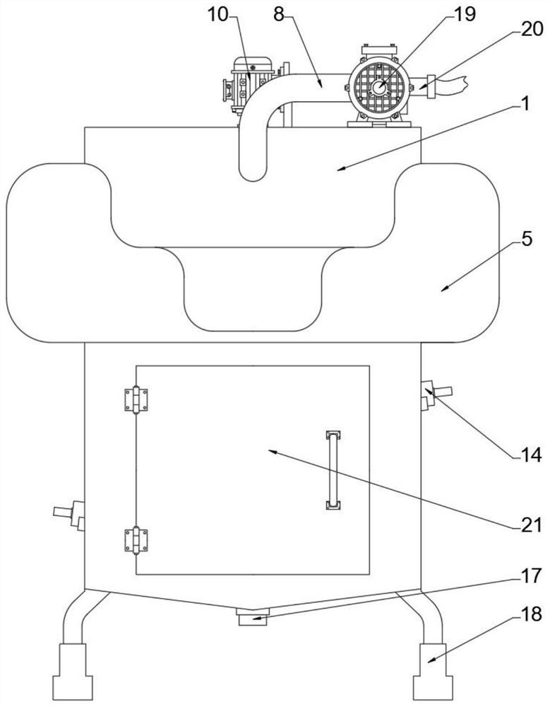
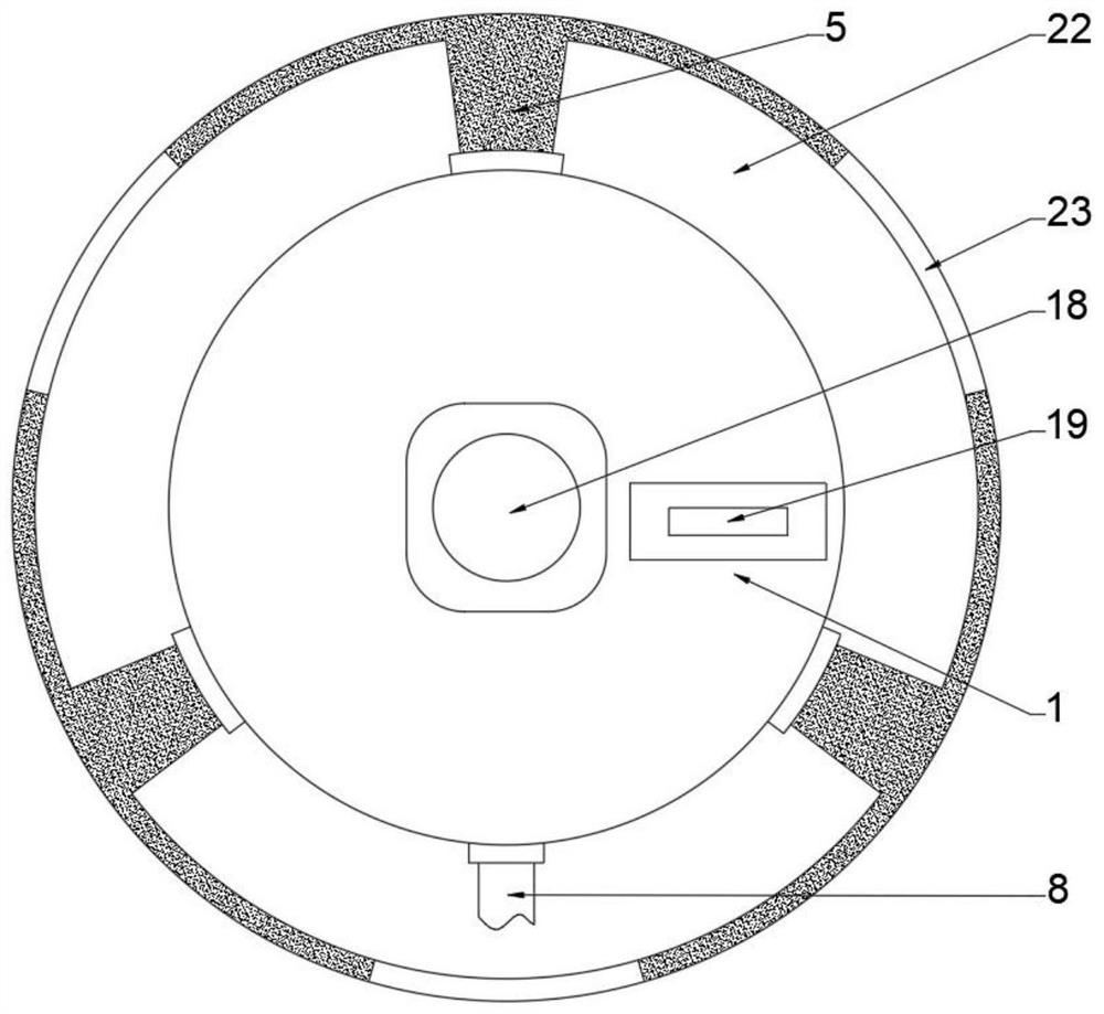
[0028] refer to Figure 1-8 , a coolant recovery mechanism for a numerically controlled machine tool, comprising a casing 1, a servo motor 10 and a water pump 19, the inside of the casing 1 is fixedly connected with a filter screen 2, and the top of the filter screen 2 is provided with a slag removal mechanism 3, and the casing 1 There is a first slag outlet 4 matching with the slag removal mechanism 3 in the inside, and the outer side of the casing 1 is fixedly connected with a collection tank 5, and the slag removal mechanism 3 and the filter screen 2 are connected by a connecting rod 6, and the connecting rod 6 runs through the The slag removal mechanism 3 and the filter screen 2, the connecting rod 6 is fixedly connected with the slag removal mechanism 3 and is rotatably connected with the filter screen 2 through the bearing sleeve, the top bolt of the casing 1 is fixedly connected with the servo motor 10, and the output shaft of the servo motor 10 The penetrating casing 1...
Embodiment 2
[0032] refer to Figure 1-8, a coolant recovery mechanism for a numerically controlled machine tool, comprising a casing 1, a servo motor 10 and a water pump 19, the inside of the casing 1 is fixedly connected with a filter screen 2, and the top of the filter screen 2 is provided with a slag removal mechanism 3, and the casing 1 There is a first slag outlet 4 matching with the slag removal mechanism 3 in the inside, and the outer side of the casing 1 is fixedly connected with a collection tank 5, and the slag removal mechanism 3 and the filter screen 2 are connected by a connecting rod 6, and the connecting rod 6 runs through the The slag removal mechanism 3 and the filter screen 2, the connecting rod 6 is fixedly connected with the slag removal mechanism 3 and is rotatably connected with the filter screen 2 through the bearing sleeve, the top bolt of the casing 1 is fixedly connected with the servo motor 10, and the output shaft of the servo motor 10 The penetrating casing 1 ...
Embodiment 3
[0040] refer to Figure 1-8 , a coolant recovery mechanism for a numerically controlled machine tool, comprising a casing 1, a servo motor 10 and a water pump 19, the inside of the casing 1 is fixedly connected with a filter screen 2, and the top of the filter screen 2 is provided with a slag removal mechanism 3, and the casing 1 There is a first slag outlet 4 matching with the slag removal mechanism 3 in the inside, and the outer side of the casing 1 is fixedly connected with a collection tank 5, and the slag removal mechanism 3 and the filter screen 2 are connected by a connecting rod 6, and the connecting rod 6 runs through the The slag removal mechanism 3 and the filter screen 2, the connecting rod 6 is fixedly connected with the slag removal mechanism 3 and is rotatably connected with the filter screen 2 through the bearing sleeve, the top bolt of the casing 1 is fixedly connected with the servo motor 10, and the output shaft of the servo motor 10 The penetrating casing 1...
PUM
 Abstract
Description
Claims
Application Information
 - R&D
- Intellectual Property
- Life Sciences
- Materials
- Tech Scout
- Unparalleled Data Quality
- Higher Quality Content
- 60% Fewer Hallucinations
Browse by: Latest US Patents, China's latest patents, Technical Efficacy Thesaurus, Application Domain, Technology Topic, Popular Technical Reports.
© 2025 PatSnap. All rights reserved.Legal|Privacy policy|Modern Slavery Act Transparency Statement|Sitemap|About US| Contact US: help@patsnap.com