Redundancy system, redundancy management method and readable storage medium

A redundancy management and redundancy technology, applied in the field of data transmission, can solve the problems of complex wiring, poor system flexibility, and low bus utilization, and achieve the effect of simplifying wiring complexity, improving speed, and improving bus utilization.

Pending Publication Date: 2021-12-28
GUANGDONG HUITIAN AEROSPACE TECH CO LTD
View PDF6 Cites 0 Cited by
  • Summary
  • Abstract
  • Description
  • Claims
  • Application Information

AI Technical Summary

Problems solved by technology

[0003] In general, the controllers in traditional redundancy systems mostly adopt an integrated design. In addition to the signal acquisition, data processing, and control algorithm implementation related to actuation control, the redundancy management algorithms are all implemented on the controller, which affects the computing power of the controller. The requirements are high. In addition, the integrated design has poor portability. It is difficult to port the code when replacing the program (such as changing the MCU chip type), and the system has poor flexibility.
In addition, the existing redundancy systems often use point-to-point connection or dedicated bus, the wiring is complicated and the bus utilization rate is not high

Method used


Image

  • Redundancy system, redundancy management method and readable storage medium
  • Redundancy system, redundancy management method and readable storage medium
  • Redundancy system, redundancy management method and readable storage medium

Examples


no. 1 example

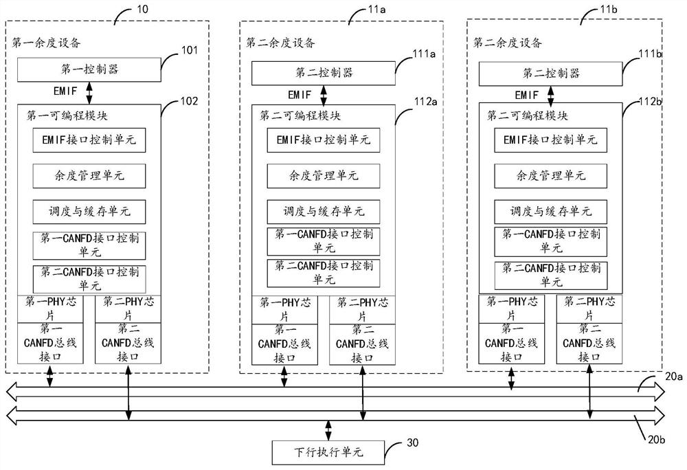
[0032] figure 1 It is a schematic structural diagram of the redundancy system of the first embodiment of the present application. Such as figure 1 The shown redundancy system comprises a first redundancy device 10, 2 second redundancy devices 11a, 11b. In other implementation manners, the number of second redundancy devices 11 in the redundancy system may also be other positive integers, such as 1, 3, 4 or more.

[0033] Such as figure 1 As shown, the first redundancy device 10 includes a first controller 101 and a first programmable module 102 . In one embodiment, the first controller 101 and the first programmable module 102 in the first redundancy device 10 are respectively disposed on different circuit boards and connected through a flexible circuit board. In other implementation manners, the first programmable module 102 may also be disposed on the main control circuit board where the first controller 101 is located.

[0034] Wherein, the first controller 101 is conn...

no. 2 example

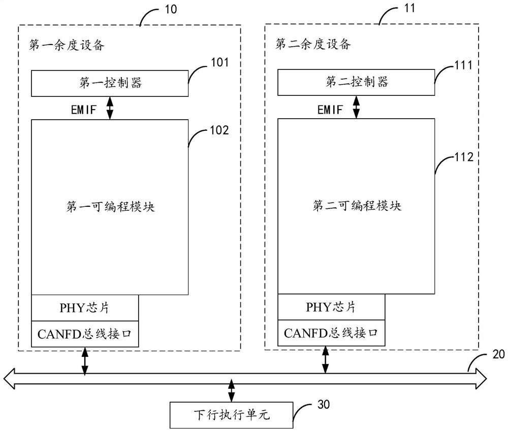
[0051] figure 2 It is a schematic structural diagram of the redundancy system of the second embodiment of the present application. Such as figure 2 As shown, in this embodiment, the redundancy system includes a first redundancy device 10 and a second redundancy device 11 .

[0052] Wherein, the first redundancy device 10 includes a first controller 101 and a first programmable module 102 . The first controller 101 is connected to the first programmable module 102 through a communication interface such as EMIF.

[0053] In one embodiment, the first controller 101 is used to complete functions such as data acquisition and processing of internal redundancy devices such as speed sensors, air data sensors, and displacement sensors, implementation of motion control algorithms, state monitoring, and internal redundancy management. And the communication data, such as the first cross-channel data that needs to be cross-transmitted, is sent to the first programmable module 102 thro...

no. 3 example

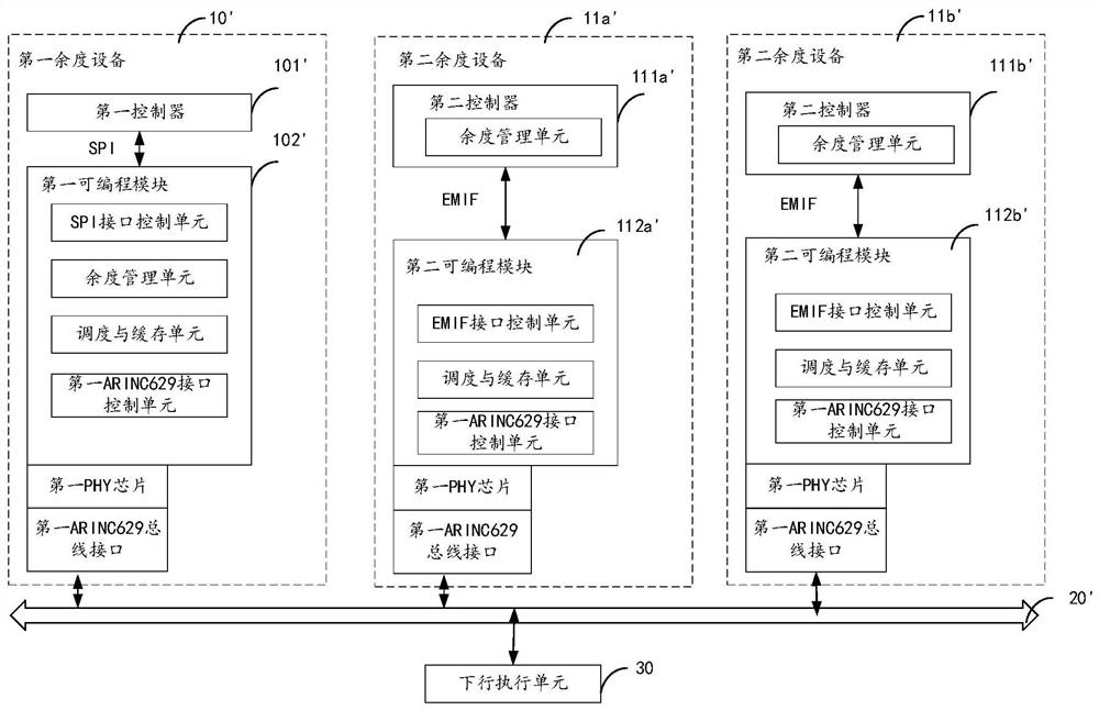
[0062] image 3 It is a schematic structural diagram of the redundancy system of the third embodiment of the present application. Such as image 3 The shown redundancy system comprises a first redundancy device 10', 2 second redundancy devices 11a', 11b'. Such as image 3 The first redundancy device 10' shown is the same as figure 1 The structure and working principle of the first redundancy equipment 10 shown are basically the same, the difference is that the first redundancy equipment 10' communicates with the second redundancy equipment 11a', 11b' through an ARINC629 type redundancy bus 20' For data interaction, the first controller 101' in the first redundancy device 10' and the first programmable module 102' perform data interaction through SPI. Such as image 3 The second redundancy device 11a', 11b' shown is the same as figure 1 The structure and working principle of the second redundancy device 11a shown are basically the same, the difference is that the redundan...


PUM


Abstract

The invention provides a redundancy system, a redundancy management method and a readable storage medium. The redundancy system comprises a first redundancy equipment and at least one second redundancy equipment. The first redundancy equipment comprises a first controller and a first programmable module; the first controller is connected with the first programmable module through a communication interface; the first programmable module performs data transmission with the at least one second redundancy equipment and a downlink execution unit through at least one redundancy bus; wherein at least two kinds of data are respectively transmitted between the first programmable module and the at least one second redundancy equipment and between the first programmable module and the downlink execution unit through the same redundancy bus in different time periods. The programmable module serves as a function extension peripheral of the controller, the data processing speed and the system flexibility can be improved, in addition, at least two kinds of data are transmitted in different time periods through the same redundancy bus, the bus utilization rate can be improved, and the wiring complexity is simplified.

Description

technical field [0001] The present application relates to the technical field of data transmission, in particular to a redundancy system, a redundancy management method and a readable storage medium. Background technique [0002] Redundancy technology is one of the design methods for system or equipment to obtain high reliability, high security and high survivability. Especially when the quality and reliability of components or parts are relatively low, and the reliability requirements of equipment cannot be met by general design, redundancy technology has important application value. [0003] In general, the controllers in traditional redundancy systems mostly adopt an integrated design. In addition to the signal acquisition, data processing, and control algorithm implementation related to actuation control, the redundancy management algorithms are all implemented on the controller, which affects the computing power of the controller. The requirements are high. In addition...

Claims


Application Information

Patent Timeline
IPC IPC(8): G06F30/32
CPCG06F30/32Y02P90/02
Inventor 赵德力谢晰波陶永康
Owner GUANGDONG HUITIAN AEROSPACE TECH CO LTD
Why Eureka
Try Eureka