Magnetron sputtering device

A technology of a magnetron sputtering device and a sputtering chamber, which is applied in the field of sputtering and can solve the problems of low overall target utilization and less sputtering volume

Pending Publication Date: 2021-12-31
北海惠科半导体科技有限公司
View PDF0 Cites 2 Cited by
  • Summary
  • Abstract
  • Description
  • Claims
  • Application Information

AI Technical Summary

Problems solved by technology

[0004] The purpose of this application is to provide a magnetron sputtering device to improve the probl

Method used


Image

  • Magnetron sputtering device
  • Magnetron sputtering device
  • Magnetron sputtering device

Examples


Example Embodiment

[0028] It should be understood that the terminology used herein, the specific structural and functional details disclosed are only for describing specific embodiments and are representative, but the present application may be embodied in many alternative forms and should not be construed as only Limited by the embodiments set forth herein.

[0029] In the description of this application, the terms "first" and "second" are only used for description purposes, and cannot be understood as indicating relative importance, or implicitly indicating the number of indicated technical features. Thus, unless otherwise stated, features defined as "first" and "second" may expressly or implicitly include one or more of the features; "plurality" means two or more. The term "comprising" and any variations thereof mean non-exclusive inclusion, possibly the presence or addition of one or more other features, integers, steps, operations, elements, components, and / or combinations thereof.

[0030...


PUM


Abstract

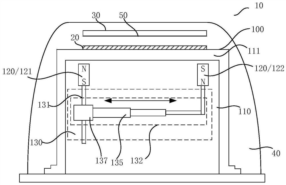
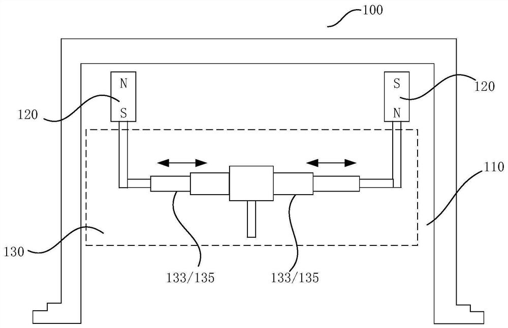
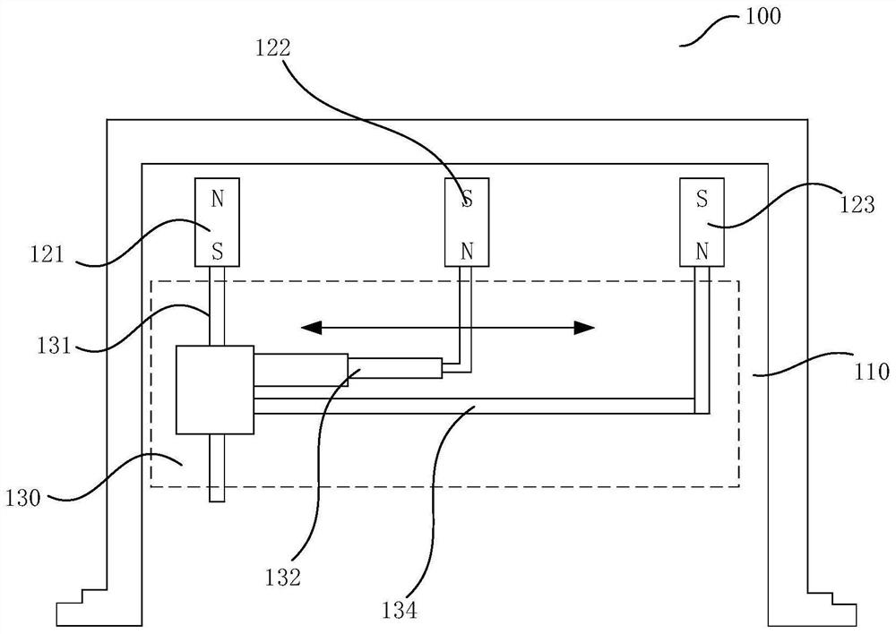
The invention discloses a magnetron sputtering device. The magnetron sputtering device comprises a base table, a target material, a sputtering cavity and a magnetic field regulator. The sputtering cavity is used for sealing the base table, the target material and the magnetic field regulator, the magnetic field regulator comprises a first cavity, at least two magnets and a magnet spacing control module, the at least two magnets are arranged in the first cavity, and the magnetic poles of the tops of the two magnets are opposite. The magnet spacing control module is connected with the two magnets and controls the spacing change between the two magnets. The magnet spacing control module controls one or two of the two magnets to move so as to change the distance between the two magnets, so that the size of a magnetic field between the two magnets is continuously changed. The magnetic field between the two magnets is continuously changed by continuously changing the distance between the magnets, so that the problems that the sputtering amount in the middle area of the target material is small, and the overall utilization rate of the target material is low are solved.

Description

technical field [0001] The present application relates to the field of sputtering technology, in particular to a magnetron sputtering device. Background technique [0002] Magnetron sputtering devices are widely used in the processing of integrated circuits. Magnetron sputtering coatings are based on two-pole DC sputtering and apply an orthogonal electromagnetic field above the target. The magnetic field constrains electrons to move spirally around the target surface. , a method to increase the probability of electrons colliding with argon, and improve the gas ionization rate and sputtering yield. [0003] Due to its excellent controllability and film bonding force, it is widely used in semiconductor manufacturing processes. Among the many characteristics of the film, the uniformity is an important index to measure the quality of the film and the performance of the machine. The uniformity of the film is related to many factors, including gas uniformity, magnetic field unifo...

Claims


Application Information

Patent Timeline
IPC IPC(8): C23C14/35
CPCC23C14/35
Inventor 张浩王国峰
Owner 北海惠科半导体科技有限公司
Why Eureka
Try Eureka