Biomass energy particle preparation device

A preparation device and biomass energy technology, applied in grain processing, solid separation, sieving and other directions, can solve the problems of inconvenient processing, different particle sizes for cutting, and many accumulated materials, etc. The effect of bending offset and high machining efficiency

Inactive Publication Date: 2022-01-04
李冠群
View PDF0 Cites 0 Cited by
  • Summary
  • Abstract
  • Description
  • Claims
  • Application Information

AI Technical Summary

Problems solved by technology

[0004] Aiming at the deficiencies of the prior art, the present invention provides a biomass granule preparation device, which solves the problem that the cutting device used in the current biomass granule preparation process is usually unable to limit the particle diameter after cutting. The uneven material speed and the different sizes of the cut particles are inconvenient for subsequent processing, and the accumulation of more materials during cutting is prone to clogging.

Method used


Image

  • Biomass energy particle preparation device
  • Biomass energy particle preparation device
  • Biomass energy particle preparation device

Examples


Embodiment 1

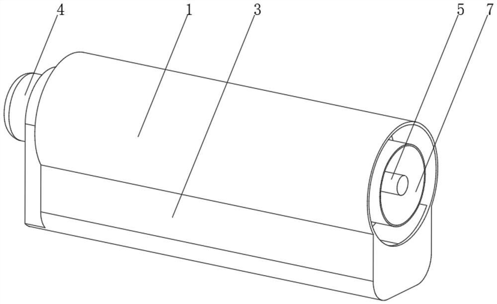
[0040] see Figure 1-4 , the present invention provides a technical solution: a biomass particle preparation device, specifically comprising:

[0041] An external fixing cylinder 1, the bottom of the external fixing cylinder 2 is provided with a storage shell 3, and one end of the external fixing cylinder 2 is provided with a driving device 4;

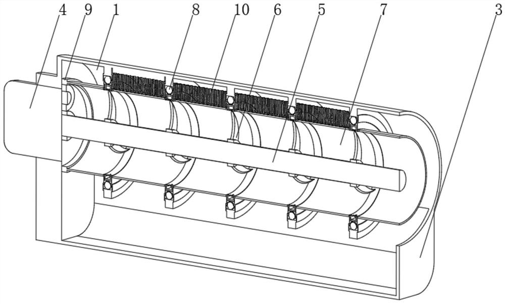
[0042] Drive shaft 5, one end of the drive shaft 5 is connected to the drive device 4, the outside of the drive shaft 5 is provided with cutting knives 6, and the cutting knives 6 are arranged in multiple groups and evenly distributed on the drive shaft 5;

[0043] Screen cylinder 7, the screen cylinder 7 is connected with the external fixed cylinder 2 through the rotating device 8, the inner gear 9 is arranged at one end of the screen cylinder 7, and the end of the drive shaft 5 close to the inner gear 9 passes through the gear set and the inner gear 9 transmission connection;

[0044] A cleaning device 10, the cleaning device 10 is...

Embodiment 2

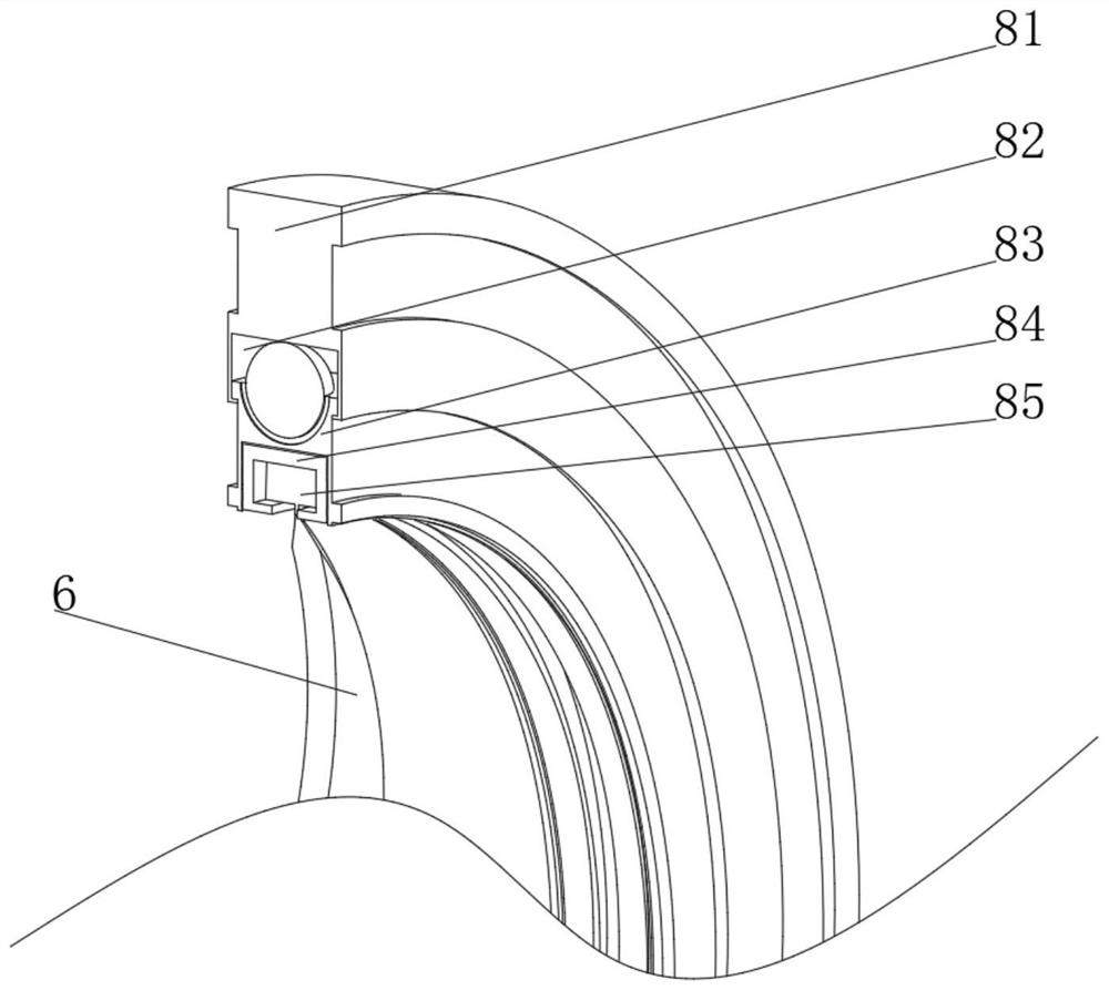
[0049] see Figure 1-6 On the basis of Embodiment 1, the present invention provides a technical solution: the cleaning device 10 includes:

[0050] Cleaning brush 101, the top of the cleaning brush 101 is fixed on the inner wall of the outer fixed cylinder 1, and the bottom of the cleaning brush 101 is closely attached to the surface of the screen cylinder 7

[0051] A tup 102, one end of the tup 102 is fixed on the inner wall of the outer fixed cylinder 1 through a rotating support 103, and the tup 102 can rotate around the rotating support 103;

[0052] Spring leaf 104, the spring leaf 104 is fixed on the inner wall of the outer fixing cylinder 1, and the bottom of the spring leaf 104 is fixedly connected with the end of the hammer head 102 away from the rotating support 103;

[0053] A rotating ring 105, the rotating ring 105 is sleeved on the hammer head 102 and can rotate on the hammer head 102, and the outer side of the rotating ring 105 is provided with a spherical pro...


PUM


Abstract

The invention discloses a biomass energy particle preparation device, which specifically comprises an outer fixed cylinder, the bottom of the outer fixed cylinder is provided with a storage shell, and one end of the outer fixed cylinder is provided with a driving device; a driving shaft, wherein one end of the driving shaft is connected with the driving device, a plurality of groups of cutting knives are arranged on the outer side of the driving shaft, and the cutting knives are uniformly distributed on the driving shaft; a screen cylinder which is connected with the outer fixed cylinder through a rotating device, an inner gear ring is arranged at one end of the screen cylinder, and the end, close to the inner gear ring, of the driving shaft is in transmission connection with the inner gear ring through a gear set; and a cleaning device which is arranged on the inner wall of the outer fixed cylinder. The invention relates to the technical field of biomass energy. According to the biomass energy particle preparation device provided by the invention, the maximum diameter of cut particles can be conveniently controlled, the situation that follow-up machining is affected by particles with the large diameter in the particles is avoided, blockage caused by material accumulation during cutting can be avoided, the failure rate is low, and the machining efficiency is high.

Description

technical field [0001] The invention relates to the technical field of biomass energy, in particular to a biomass energy granule preparation device. Background technique [0002] According to the definition of the International Energy Agency, biomass refers to various organisms formed through photosynthesis, including all animals, plants and microorganisms. Biomass energy is the energy form of solar energy stored in biomass in the form of chemical energy. It has always been It is one of the important energy sources that human beings rely on for survival. It is the fourth largest energy source after coal, oil, and natural gas, and occupies an important position in the entire energy system. At present, in the process of preparing biomass energy particles, the cutting device used usually cannot limit the diameter of the cut particles. Due to the uneven feeding speed, the cut particles are of different sizes, which is inconvenient for subsequent processing and accumulates during...

Claims


Application Information

Patent Timeline
Patent Type & Authority Applications(China)
IPC IPC(8): B02C18/14B02C18/16B02C23/16B07B1/52B07B1/50
CPCB02C18/14B02C18/16B02C23/16B07B1/522B07B1/50B02C2023/165
Inventor 李冠群
Owner 李冠群
Why Eureka
Try Eureka