Intelligent movable pipeline hoisting device for petroleum pipeline laying
A technology for oil pipelines and hoisting devices, applied in auxiliary devices, welding equipment, transportation and packaging, etc., can solve problems such as welding deviation, easy shaking of oil pipelines, and influence of oil pipeline placement accuracy, and achieve the effect of convenient positioning and welding
- Summary
- Abstract
- Description
- Claims
- Application Information
AI Technical Summary
Problems solved by technology
Method used
Image

Examples
Embodiment 1
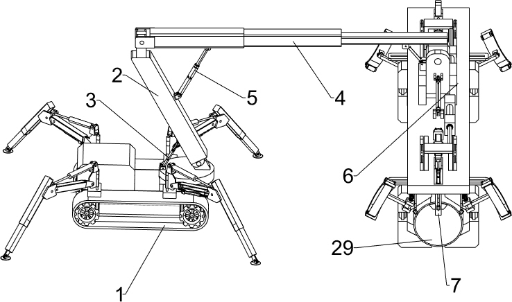
[0030] An intelligent mobile pipeline hoisting device for laying oil pipelines, such as figure 1 and figure 2 As shown, it includes a support arm 2, a first hydraulic cylinder 3, a hydraulic telescopic frame 4, a second hydraulic cylinder 5, an adjustment mechanism 6 and a balance mechanism 7, and the crawler vehicle 1 is rotatably provided with a support arm 2. The first hydraulic cylinder 3 is provided in a rotating manner, and the first hydraulic cylinder 3 is located on the left side of the support arm 2. The telescopic end of the first hydraulic cylinder 3 is rotationally connected with the lower part of the left wall of the support arm 2. There is a hydraulic telescopic frame 4, a second hydraulic cylinder 5 is arranged in a rotating manner between the left part of the bottom surface of the hydraulic telescopic frame 4 and the upper part of the right wall of the support arm 2, and the right part of the hydraulic telescopic frame 4 is provided with an adjustment mechanis...
Embodiment 2
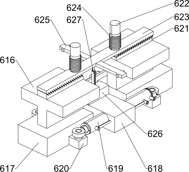
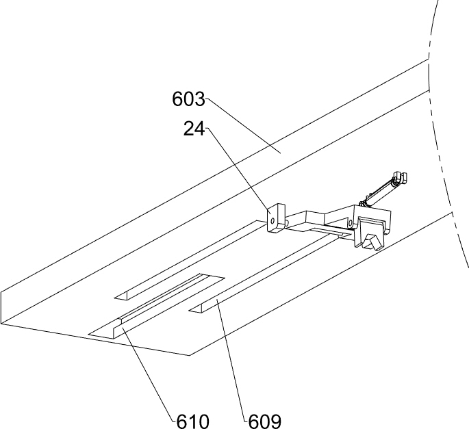
[0033] On the basis of Example 1, such as Figure 2-8 As shown, the adjustment mechanism 6 includes a turret 601, a fixed plate 602, a first mounting plate 603, a third hydraulic cylinder 604, a fourth hydraulic cylinder 605, a mounting seat 606, a fifth hydraulic cylinder 607, a mounting frame 612, a circular Sliding plate 613, fixed frame 614, hollow plate 615, T-shaped sliding plate 616, connecting plate 617, second mounting plate 618, sixth hydraulic cylinder 619, first fixing block 620, limiting parts and clamping parts, hydraulic telescopic frame The right part of the bottom surface of 4 is rotatably equipped with a turret 601, and the left and right two wall bottoms of the turret 601 are rotatably connected with a fixed plate 602, and a first mounting plate 603 is installed between the bottoms of the fixed plate 602 on the left and right sides, and the turret A third hydraulic cylinder 604 is rotatably connected between the left wall of 601 and the right part of the bot...
Embodiment 3
[0039] On the basis of Example 2, such as Figure 7 , Figure 9 and Figure 10 As shown, it also includes a servo motor 8, a first bevel gear 9, a connecting block 10, a rotating block 11, a second bevel gear 12, a rotating plate 13, a first rotating shaft 14, a second fixed block 15, and a first torsion spring 16 , arc-shaped plate 17 and anti-skid parts, the first clamping block 628 outer wall upper part of front and back both sides all is embedded with servomotor 8, the output end of servomotor 8 is equipped with the first bevel gear 9 by shaft coupling, the first bevel gear 9 of front and back both sides Two connection blocks 10 are installed on the upper part of the outer wall of a clamp block 628, and the connection block 10 is positioned at the lower side of the servo motor 8, and a rotation block 11 is installed between the two connection blocks 10 adjacent up and down by a rotating rod, and the rotation block The rotating rod on the 11 upper side is equipped with a ...
PUM
 Abstract
Description
Claims
Application Information
 - Generate Ideas
- Intellectual Property
- Life Sciences
- Materials
- Tech Scout
- Unparalleled Data Quality
- Higher Quality Content
- 60% Fewer Hallucinations
Browse by: Latest US Patents, China's latest patents, Technical Efficacy Thesaurus, Application Domain, Technology Topic, Popular Technical Reports.
© 2025 PatSnap. All rights reserved.Legal|Privacy policy|Modern Slavery Act Transparency Statement|Sitemap|About US| Contact US: help@patsnap.com