
Automatic power generation control system based on boiler waste heat

A technology of automatic power generation control and boiler waste heat, which is applied in the direction of machines/engines, sustainable manufacturing/processing, steam engine installations, etc., can solve problems such as low power generation efficiency, poor system stability, limited response speed and energy, and improve power generation efficiency , improve system stability, and reduce the effect of enterprise labor costs

Pending Publication Date: 2022-01-04
华润水泥(陆川)有限公司 +2
View PDF0 Cites 0 Cited by
  • Summary
  • Abstract
  • Description
  • Claims
  • Application Information

AI Technical Summary

Problems solved by technology

[0003] Cement kiln waste heat power generation often uses residual heat to generate electricity, and the heat source is unstable; currently, in waste heat power plants, experienced operators still rely on experienced operators to adjust the system balance to ensure stable operation of the system. Once the operator does not operate for a long time, the system will crash and jump. The manual adjustment system has poor stability and low power generation efficiency: because the heat source of the waste heat power generation system is unstable and changes at any time, this requires the operator to make adjustments in time according to the changes. Due to the limited response speed and energy of the operator, the operator's operation behavior cannot be timely. Adjustments are made according to changes in working conditions, which leads to poor system stability and low power generation efficiency

Method used


Image

  • Automatic power generation control system based on boiler waste heat
  • Automatic power generation control system based on boiler waste heat
  • Automatic power generation control system based on boiler waste heat

Examples


Embodiment Construction

[0041] It should be understood that the specific embodiments described here are only used to explain the present invention, not to limit the present invention.

[0042] The following will clearly and completely describe the technical solutions in the embodiments of the present invention with reference to the accompanying drawings in the embodiments of the present invention. Obviously, the described embodiments are only some, not all, embodiments of the present invention. Based on the embodiments of the present invention, all other embodiments obtained by persons of ordinary skill in the art without creative efforts fall within the protection scope of the present invention.

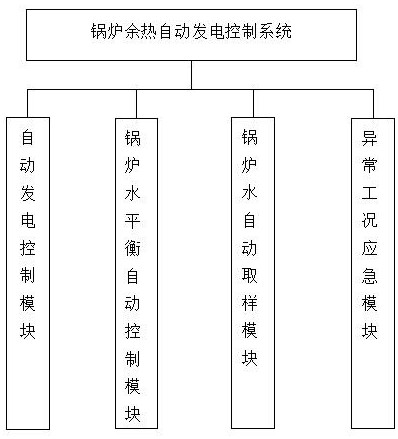
[0043] In this example, if figure 1 As shown, a boiler waste heat automatic power generation control system includes an automatic power generation control module, a boiler water balance automatic control module, a boiler water automatic sampling module and an emergency module for abnormal working condition...


PUM


Abstract

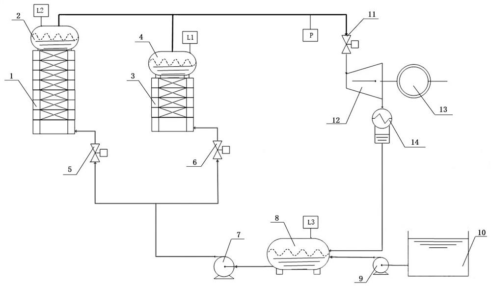
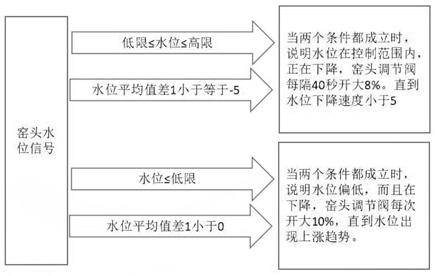
The invention discloses an automatic power generation control system based on boiler waste heat. The automatic power generation control system comprises an automatic power generation control module, a boiler water balance automatic control module, a boiler water automatic sampling module and an abnormal working condition emergency module; the automatic power generation control module can adjust a steam inlet control valve of a steam turbine according to the steam inlet pressure P of the steam turbine, and therefore the power generation amount and current of a power generator are controlled; the boiler water balance automatic control module is used for controlling the water level, and the water level is made to be within the dynamic qualified range; the boiler water automatic sampling module is used for automatically taking out surface water from a boiler drum at the kiln head or the kiln tail for testing; and the abnormal working condition emergency module is used for entering an emergency control state when the boiler water balance automatic control module is abnormal. The automatic power generation control system can completely replace an operator during normal running, full-automatic intelligent operation is achieved, the labor cost of enterprises is reduced, the system stability is improved, and the power generation efficiency is improved.

Description

technical field [0001] The invention relates to the field of waste heat power generation, in particular to a boiler waste heat automatic power generation control system. Background technique [0002] Cement kiln waste heat power generation technology is to directly recover the waste heat and waste gas discharged from the kiln head and kiln tail during the clinker calcination process of the cement kiln, and generate steam through the waste heat boiler to drive the turbine generator to generate electricity. A cement clinker production line with a daily output of 5,000 tons can use waste heat to generate electricity of 210,000 to 240,000 degrees per day, which can solve about 60% of the electricity used for clinker production, reduce the overall energy consumption of products by about 18%, and save about 25,000 tons of standard coal per year , reducing carbon dioxide emissions by about 60,000 tons. For cement production enterprises: it can greatly reduce the electricity purcha...

Claims


Application Information

Patent Timeline
Patent Type & Authority Applications(China)
IPC IPC(8): F01K27/00F01K13/00F01K11/02F01D15/10
CPCF01K27/00F01K13/00F01K11/02F01D15/10Y02E20/14Y02P80/15
Inventor 孙旭光张云军杨寿辉卢荫坤陈剑明苏文宝翁松苏乐明李健华杨东城卢志军杜海翔黄亮元韦明黄超强韦训平梁宇王宁
Owner 华润水泥(陆川)有限公司
Learn More