
Air cylinder assembly, manufacturing method of air cylinder assembly, rotary compressor and manufacturing method of rotary compressor

The technology of a rotary compressor and its production method, which is applied in the field of compressors, can solve the problems of reducing the cooling capacity and reducing the suction volume, and achieve the effects of reducing the suction specific volume, reducing the leakage, and reducing the temperature of the motor

Pending Publication Date: 2022-01-04
SHANGHAI HITACHI ELECTRICAL APPLIANCES CO LTD
View PDF0 Cites 0 Cited by
  • Summary
  • Abstract
  • Description
  • Claims
  • Application Information

AI Technical Summary

Problems solved by technology

Through the internal thermodynamic analysis of the compressor, it is found that if the internal temperature of the cylinder is too high, it will directly affect the power consumption of the compressor, and the temperature of the suction wall surface of the cylinder will directly affect the suction specific volume, reduce the suction volume, and lead to a decrease in cooling capacity.

Method used


Image

  • Air cylinder assembly, manufacturing method of air cylinder assembly, rotary compressor and manufacturing method of rotary compressor
  • Air cylinder assembly, manufacturing method of air cylinder assembly, rotary compressor and manufacturing method of rotary compressor
  • Air cylinder assembly, manufacturing method of air cylinder assembly, rotary compressor and manufacturing method of rotary compressor

Examples


Embodiment Construction

[0030] Example embodiments will now be described more fully with reference to the accompanying drawings. Example embodiments may, however, be embodied in many forms and should not be construed as limited to the embodiments set forth herein. Rather, these embodiments are provided so that this disclosure will be thorough and complete, and will fully convey the concept of the example embodiments to those skilled in the art. The same reference numerals denote the same or similar structures in the drawings, and thus their repeated descriptions will be omitted.

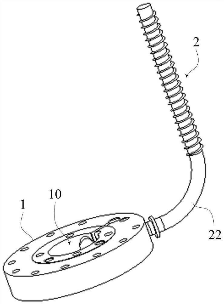
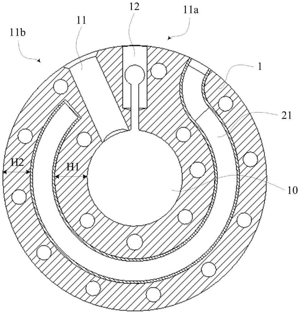
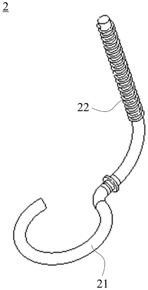
[0031] figure 1 Show the three-dimensional structure of the cylinder assembly in the embodiment, figure 2 shows the cross-sectional structure of the cylinder assembly, image 3 The three-dimensional structure of the heat pipe assembly is shown. to combine Figure 1 to Figure 3 As shown, the cylinder assembly in this embodiment mainly includes: an annular cylinder 1, the inner circumference of which is provided with a ...


PUM


Abstract

The invention relates to the technical field of compressors, and provides an air cylinder assembly, a manufacturing method of the air cylinder assembly, a rotary compressor and a manufacturing method of the rotary compressor. The air cylinder assembly comprises an annular cylinder body and a heat pipe assembly. A compression cavity is formed in the inner circumference of the annular cylinder body. The heat pipe assembly partially extends into the annular cylinder body and extends in the annular cylinder body, and an evaporation section which is embedded in the annular cylinder body and at least partially wraps the compression cavity and a condensation section which extends out of the periphery of the annular cylinder body are formed. By means of the modes that the evaporation section is embedded in the annular cylinder body and at least partially wraps the compression cavity, and the condensation section extends out of the periphery of the annular cylinder body, the compression heat in the annular cylinder body is discharged in time through the ultra-high heat conduction capacity of the heat pipe assembly, the temperature of the air cylinder assembly is reduced, the indication efficiency of the compressor is improved, air suction heating can also be reduced, the air suction specific volume can be reduced, the volume efficiency can be improved, and therefore the energy efficiency of the compressor is improved. The temperature reduction of the air cylinder assembly can further reduce the temperature of a motor, improve the efficiency of the motor, also improve the temperature field of the whole machine, and prolong the service life of each part.

Description

technical field [0001] The invention relates to the technical field of compressors, in particular to a cylinder assembly and a manufacturing method thereof, as well as a rotary compressor including the cylinder assembly and a manufacturing method thereof. Background technique [0002] The existing structure of the compressor adopts a clearance fit between the cylinder and the shell, and there is a gap between the suction wall of the cylinder and the inner wall of the shell. During the actual operation of the compressor, the gap is covered by the high-temperature refrigerant Fill with refrigeration oil. [0003] Due to the high back pressure characteristics of the rotary compressor, the gap between the suction wall of the cylinder and the inner wall of the shell is filled with a mixture of high-temperature refrigerant and refrigerating machine oil, which is not conducive to the heat dissipation of the heat generated by the compressed refrigerant in the cylinder. Through the ...

Claims


Application Information

Patent Timeline
Patent Type & Authority Applications(China)
IPC IPC(8): F04C29/00F04C29/04F04C18/356B22D19/00
CPCF04C29/00F04C29/04F04C18/356B22D19/0072
Inventor 黄波孟祥麒
Owner SHANGHAI HITACHI ELECTRICAL APPLIANCES CO LTD
Learn More