Automatic dust-free hinge hole numerical control machine

A hinge hole and CNC machine technology, applied in the direction of boring/drilling, drilling/drilling equipment, boring machine/drilling machine parts, etc., can solve the problems of low precision, low efficiency of drilling methods, etc., to improve efficiency, wide range of effects

Pending Publication Date: 2022-01-07
重庆宝标网络科技有限公司
View PDF0 Cites 0 Cited by
  • Summary
  • Abstract
  • Description
  • Claims
  • Application Information

AI Technical Summary

Problems solved by technology

[0005] In order to make up for the deficiencies of the existing technology and solve the problem that the hinge hole in the existing furniture manufacturing industry is still manually measured and drilled with a hand-held drill, such a punching method is inefficient and low in precision. CNC machine

Method used


Image

  • Automatic dust-free hinge hole numerical control machine
  • Automatic dust-free hinge hole numerical control machine
  • Automatic dust-free hinge hole numerical control machine

Examples


Embodiment 1

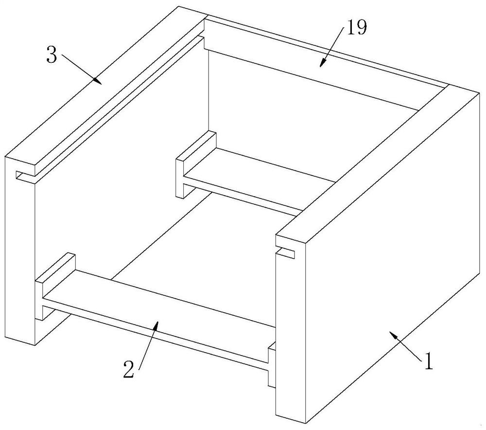
[0031] see Figure 1-4 As shown, an automatic dust-free hinge hole CNC machine includes a first bracket 1, a connecting plate 2, a second bracket 3 and a high-precision positioning unit; the two ends of the connecting plate 2 are symmetrically fixed with the first bracket 1 and the The second bracket 3; the first bracket 1 and the second bracket 3 are provided with a high-precision positioning unit;

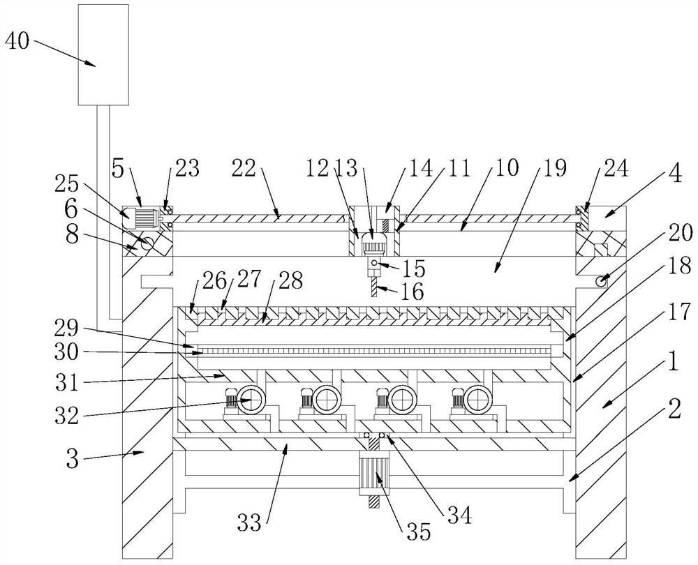
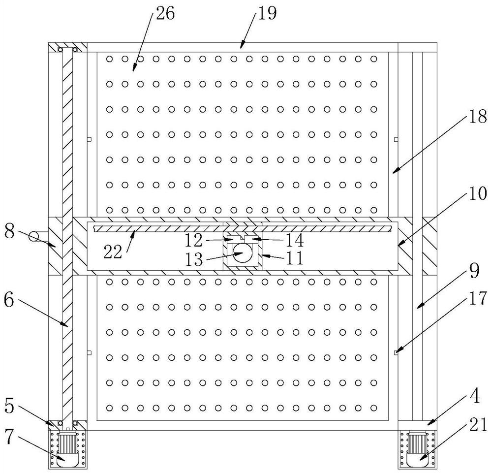
[0032]The high-precision positioning unit includes a first end plate 4, a second end plate 5 and a first screw rod 6; the first end plate 4 is symmetrically fixed at both ends of the first bracket 1; the second end plate 5 are symmetrically fixed at both ends of the second bracket 3; a slide rail 9 is fixedly connected between the second bracket 3; a slider plate 8 is buckled and connected to the slide rail 9; inside the slider plate 8 The opening is threadedly connected with a first screw mandrel 6; the first screw mandrel 6 is rotatably connected between the second end plates ...

Embodiment 2

[0043] see Figure 5 As shown in Comparative Example 1, as another embodiment of the present invention, the lower surfaces of the first bracket 1 and the second bracket 3 are fixed with a plurality of universal wheels 37; the first bracket 1 and the A handle 38 is affixed to the side of the second support 3; a plurality of hanging shafts 39 are affixed vertically on the handle 38; during work, through a plurality of universal wheels 37, it is convenient to move this numerical control machine, and it is convenient to use by the handle 38 And carry this numerical control machine, hang and hold and use other articles of this numerical control machine conveniently by hanging shaft 39.

[0044] The working principle is to program the furniture parts of different shapes through the control panel 40. After the programming is completed, put the furniture parts to be drilled on the collecting plate 26, align one end with the reset plate 19, and fix the furniture parts on the In the th...


PUM


Abstract

The invention belongs to the field of numerical control machine tools, and particularly relates to an automatic dust-free hinge hole numerical control machine which comprises a first support, a connecting plate, a second support and high-precision positioning units. A first support and a second support are symmetrically and fixedly connected to the two ends of the connecting plate; the high-precision positioning units are arranged on the first support and the second support; the high-precision positioning unit comprises a first end plate, a second end plate and a first screw rod; the first end plates are symmetrically and fixedly connected to the two ends of the first support; and the second end plates are symmetrically and fixedly connected to the two ends of the second support. A third motor drives a third screw rod to rotate at high precision, a first motor drives the first screw rod to rotate at high precision, and therefore high-precision free movement in the two perpendicular directions can be achieved. The third motor and the first motor controlled through signals can be matched with the programming program of a control panel, therefore, high-precision and high-efficiency trepanning processing can be carried out on batch furniture parts through the programming program.

Description

technical field [0001] The invention relates to the field of numerical control machine tools, in particular to an automatic dust-free hinge hole numerical control machine. Background technique [0002] CNC machine is a kind of equipment that realizes precise movements under the control of numbers and instructions, and is widely used in production and processing fields. [0003] The existing numerical control machine drives the screw rod through the servo motor to carry out precise movement and positioning, and realizes automatic positioning and automatic movement to the positioning position through programming. [0004] The hinge holes in the existing furniture manufacturing industry are still manually measured and drilled with a hand-held drill, which is inefficient and low-precision; therefore, an automatic dust-free hinge hole numerical control machine is proposed to solve the above problems. Contents of the invention [0005] In order to make up for the deficiencies o...

Claims


Application Information

Patent Timeline
IPC IPC(8): B23B41/02B23B47/00
CPCB23B41/02B23B47/00
Inventor 杨胡容
Owner 重庆宝标网络科技有限公司
Why Eureka
Try Eureka