Spiral solar structure

A solar energy and spiral technology, applied in the field of solar energy, can solve the problems of low sunlight collection efficiency, large solar equipment construction area, and low sunlight collection area, so as to improve lighting, improve utilization efficiency, and reduce floor space Effect

Pending Publication Date: 2022-01-07
杨茜茜
View PDF0 Cites 0 Cited by
  • Summary
  • Abstract
  • Description
  • Claims
  • Application Information

AI Technical Summary

Problems solved by technology

[0004] However, the current solar panels or heat collecting tubes do not have a high collection area for sunlight, so the collection efficiency for sunlight is not high, and a large equipment construction area is required for the utilization of solar energy

Method used


Image

  • Spiral solar structure
  • Spiral solar structure
  • Spiral solar structure

Examples


Embodiment 1

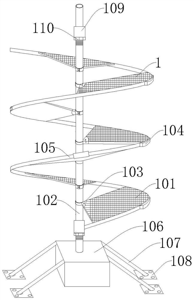
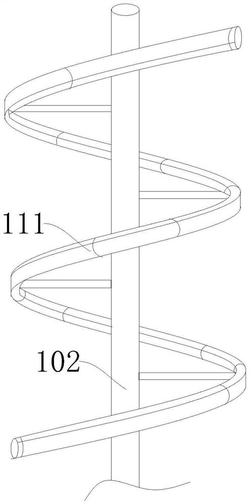
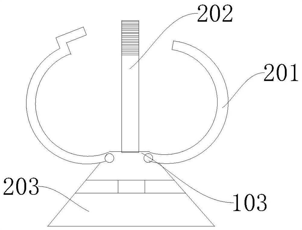
[0034] Please refer to Figure 1 to Figure 4 , figure 1 It is a schematic diagram of a spiral solar mechanism according to an embodiment of the present invention; figure 2 It is a schematic diagram of the vacuum heat collecting tube 111 of the embodiment of the present invention; image 3 It is a schematic diagram of the connector 103 according to the embodiment of the present invention; Figure 4 It is a schematic diagram of the clamping member 104 according to the embodiment of the present invention. The spiral solar structure provided by this embodiment can increase the area for collecting sunlight, improve the lighting degree, improve the utilization efficiency of solar radiation energy, and reduce the occupied space.

[0035] A spiral solar structure includes a mounting frame 102 and a solar energy conversion component. The solar energy conversion component is mounted on the mounting frame 102 and extends in a spiral shape along the length direction of the mounting fr...

Embodiment 2

[0038] In some embodiments of the invention, please refer to figure 1 , the above-mentioned solar energy conversion assembly includes a plurality of photovoltaic panels 1 , the plurality of photovoltaic panels 1 are sequentially arranged at intervals along the length direction of the installation frame 102 , and the plurality of photovoltaic panels 1 are arranged in a spiral.

[0039] Optionally, the photovoltaic panel 1 can be a conventionally known one in the prior art, wherein one end of the photovoltaic panel 1 is installed on the side of the mounting member, and a plurality of photovoltaic panels 1 are sequentially arranged at intervals along the length direction of the mounting frame 102 , and a plurality of photovoltaic panels 1 are arranged in a spiral, so that light can be irradiated to the photovoltaic panels 1 below through the gaps between different photovoltaic panels 1, thereby ensuring the area receiving light. Wherein, the height difference between two adjacent...

Embodiment 3

[0041] In some embodiments of the invention, please refer to figure 1 , the photovoltaic panel 1 includes a board body 101 and a connector 103 , one end of the connector 103 is mounted on the end of the board body 101 , and the other end is detachably connected to the mounting frame 102 .

[0042] Optionally, the connector 103 can be a buckle, and after being connected to the mounting frame 102 by the snap, it can be locked by a bolt and a screw. The board body 101 can be disassembled for transportation, which is convenient for transportation and ensures its safety. At the same time, it is also convenient to disassemble the board body 101 for maintenance during use.


PUM


Abstract

The invention provides a spiral solar structure, and relates to the technical field of solar energy. The spiral solar energy structure comprises a mounting rack and a solar energy conversion component, wherein the solar energy conversion component is installed on the mounting rack and spirally extends along the length direction of the mounting rack. According to the spiral solar structure, the sunlight collecting area can be increased, the lighting degree is improved, the utilization efficiency of solar radiation energy is improved, and the occupied space is reduced.

Description

technical field [0001] The invention relates to the technical field of solar energy, in particular to a spiral solar structure. Background technique [0002] Solar energy is a renewable energy source. Refers to the sun's heat radiation energy, the main performance is often said that the sun's rays. In modern times, it is generally used to generate electricity or provide energy for water heaters. Solar energy is both primary energy and renewable energy. It is rich in resources, can be used for free, does not need to be transported, and has no pollution to the environment. It has created a new life form for human beings, and brought society and human beings into an era of saving energy and reducing pollution. [0003] At present, there are mainly photothermal utilization and photoelectric utilization. Among them, the basic principle of photothermal utilization is to collect solar radiation energy and convert it into heat energy through the interaction with matter for util...

Claims


Application Information

Patent Timeline
IPC IPC(8): F24S10/40F24S10/70F24S25/61H02S20/10
CPCF24S10/40F24S10/70F24S25/61H02S20/10Y02E10/44Y02E10/47Y02E10/50
Inventor 杨茜茜
Owner 杨茜茜
Why Eureka
Try Eureka