Food package sealing performance detection system
A sealing detection and food packaging technology, which is applied in the field of sealing detection equipment, can solve the problems of low detection efficiency, low work efficiency, complex detection equipment system, etc., and achieve high accuracy of detection results, accelerated drying speed, and high detection efficiency Effect
- Summary
- Abstract
- Description
- Claims
- Application Information
AI Technical Summary
Problems solved by technology
Method used
Image

Examples
Embodiment 1
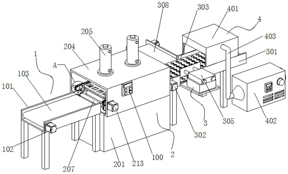
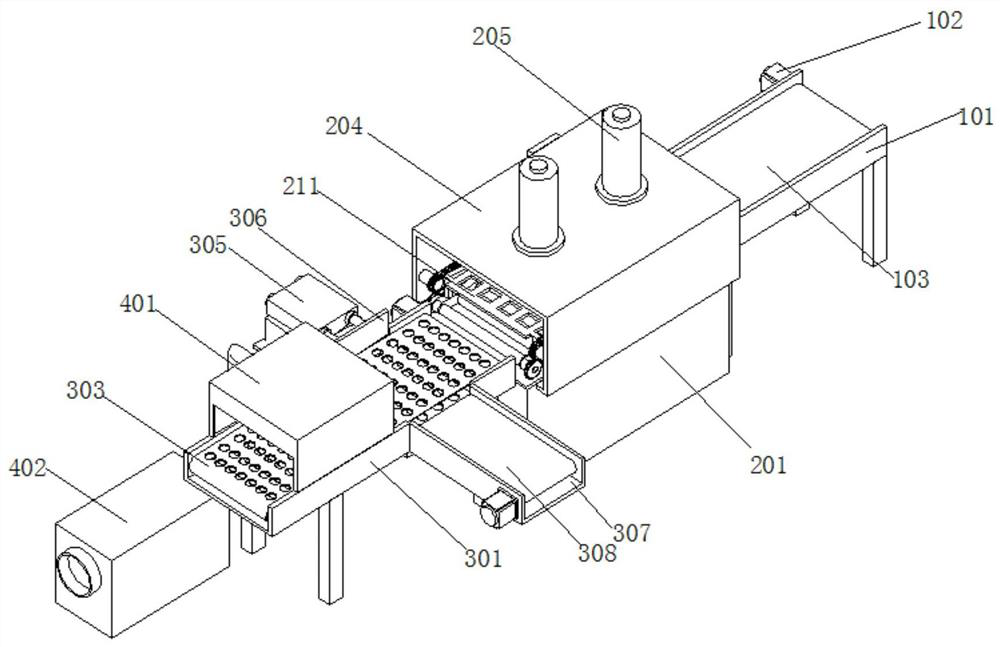
[0039] This embodiment 1 introduces a food packaging airtightness detection system, refer to the attached figure 1 And attached figure 2 , which includes a food packaging bag feeding device 1, a sealing detection mechanism 2, a sorting mechanism 3 and a draining and drying device 4.
[0040] Wherein, food packaging bag feeding device 1 comprises the first U-shaped transmission frame 101, the left and right ends of the first U-shaped transmission frame 101 are provided with belt transmission rollers (not shown in the figure), the first U-shaped transmission frame The front side of 101 is provided with a first servo motor 102, the output shaft of the first servo motor 102 extends into the first U-shaped transmission frame 101 and is connected with one of the belt transmission rollers, and the second belt transmission roller is arranged between the two belt transmission rollers. A conveyor belt 103 .
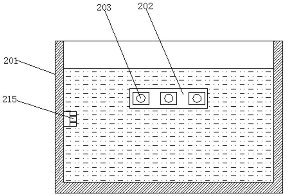
[0041] Reference attached image 3 , the leak detection mechanism 2 inclu...
Embodiment 2
[0046] Example 2 introduces a food packaging airtightness detection system improved on the basis of Example 1. Its similarities with Example 1 will not be described again. For the differences, refer to the attached Figure 9 .
[0047] First of all, the present embodiment 2 is also connected with several horizontal hot-air branch pipes 405 at intervals on the hot-air pipe 403 in the drying box 401, and the lower surface of each hot-air branch pipe 405 is provided with a plurality of hot-air outlets 404, and its hot-air branch pipe 405 The above-mentioned design can make the hot air discharged from the hot air pipe 403 blow to the soaked packaging bag more comprehensively, thereby speeding up the drying process.
[0048] In addition, the present embodiment 2 is also provided with a wind power adjustment switch 4021 and a temperature adjustment knob 4022 on the front side of the hot air blower 402, the wind power of the hot air blower can be adjusted by the wind power adjustment...
PUM
| Property | Measurement | Unit |
|---|---|---|
| Height | aaaaa | aaaaa |
Abstract
Description
Claims
Application Information
PatSnap Eureka turns technology decisions into work you can execute. Powered by our Innovation Knowledge Graph, it runs expert workflows across engineering, life sciences, materials and intellectual property. Get your review-ready output in minutes.


