Two-stage oily sludge pyrolysis reaction device

A technology for pyrolysis reaction and sludge, which is used in pyrolysis treatment of sludge, petroleum industry, special forms of dry distillation, etc. It can solve the problem of sticking or even deformation in the viscous zone of sludge, obvious thermal hysteresis effect, and low heat transfer efficiency. problem, to achieve the effect of large feed adaptability, prolong reaction time and improve pyrolysis effect

Pending Publication Date: 2022-01-11
BEIJING HANGTIAN XINFENG MECHANICAL EQUIP
View PDF4 Cites 0 Cited by
  • Summary
  • Abstract
  • Description
  • Claims
  • Application Information

AI Technical Summary

Problems solved by technology

However, in the process of moving with the chain plate, due to the small turning range of the material, the heat transfer efficiency is low, the internal and external thermal hysteresis effect of the material is obvious, and uneven heating is prone to occur.
The auger-type pyrolysis furnace has good material turning effect, remarkable heat and mass transfer, and uniform heating of materials, but the liquid content of the feed is strictly controlled, and the spiral is easy to coke, which is prone to the risk of stagnation or even deformation in the sludge sticky area.

Method used


Image

  • Two-stage oily sludge pyrolysis reaction device
  • Two-stage oily sludge pyrolysis reaction device
  • Two-stage oily sludge pyrolysis reaction device

Examples


Embodiment 1

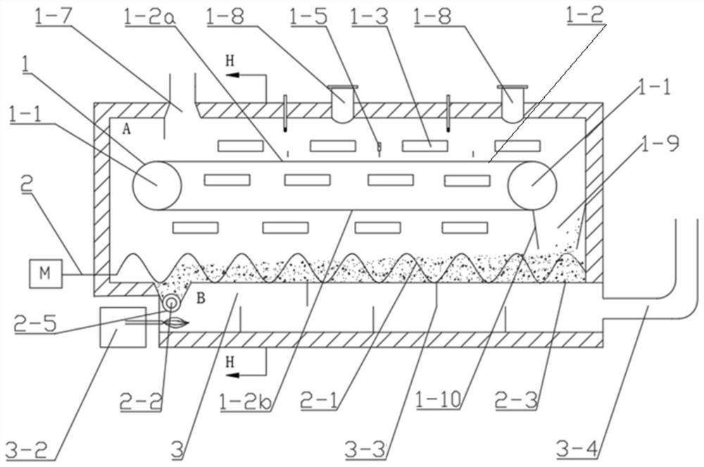
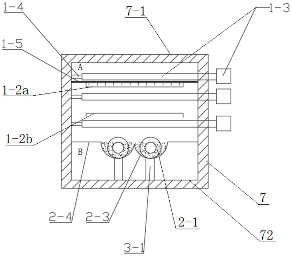
[0039] A two-stage pyrolysis reaction device for oily sludge such as figure 1As shown, it consists of the upper chain plate reactor 1 and the lower auger reactor 2. The upper chain plate reactor 1 is equipped with a transmission assembly for carrying materials to move. The transmission assembly includes two transmission sprockets 1-1 rotatably connected to the chain plate and a chain plate 1-2 built on the two transmission wheels. The two transmission sprockets 1-1 are respectively located at both ends of the upper chain plate reactor 1 to tension the chain plates 1-2, and the chain plates are arranged horizontally along the moving direction. Radiant tube heaters 1-3 are arranged between the upper chain plate 1-2a of the upper chain plate reactor 1 and the furnace roof, and the radiant tube heaters 1-3 are evenly distributed at a certain distance along the running direction of the chain plate. The mouth end is installed on the inner wall of one side of the furnace, the other ...


PUM


Abstract

A two-stage pyrolysis reaction device for oily sludge comprises a pyrolysis device shell (7), which comprises a furnace body shell (7-1) and a furnace body inner container (7-2), an upper-layer chain plate reactor (1) is arranged in the furnace body inner container (7-2), and the two-stage pyrolysis reaction device is characterized in that a lower-layer auger reactor (2) is further arranged below the upper-layer chain plate reactor (1); a material scraping plate (1-10) is arranged below the material moving tail end of the upper-layer chain plate reactor (1), and the material scraping plate (1-10) has a set length and is used for scraping materials adhered to the upper-layer chain plate reactor (1) and preventing the materials entering the lower-layer auger reactor (2) from being accumulated. According to the invention, the chain plate reactor and the auger type pyrolysis reactor are organically connected together through the ingeniously designed material collecting hopper, and the pyrolysis is more sufficient than reaction of a conventional pyrolysis furnace.

Description

technical field [0001] The invention relates to a two-stage pyrolysis reaction device for oily sludge, which relates to the field of pyrolysis, in particular to a pyrolysis reaction device for oily sludge. [0002] technical background [0003] As a very promising technology in the field of oily sludge pyrolysis, pyrolysis can not only recover petroleum resources, but also recover heat energy by using pyrolysis gas to achieve harmless treatment of oily sludge. This technology has also been vigorously promoted in major oil fields. At present, the oily sludge pyrolysis treatment devices mainly include rotary type, chain plate type, auger type, etc. These devices have problems such as serious coking, low thermal efficiency, poor stability, and substandard treatment in the actual treatment process to varying degrees. Rotary pyrolysis furnace is gradually being replaced by chain plate type and auger type due to poor sealing, low thermal efficiency, difficulty in continuous operat...

Claims


Application Information

Patent Timeline
Patent Type & Authority Applications(China)
IPC IPC(8): C02F11/10C10B53/00C10B49/04
CPCC02F11/10C10B53/00C10B49/04Y02W10/40
Inventor 揭业斐陈启
Owner BEIJING HANGTIAN XINFENG MECHANICAL EQUIP
Why Eureka
Try Eureka