Composite anti-splitting continuous sucker rod and preparation device and preparation method

A technology for preparing equipment and sucker rods, which is applied in chemical instruments and methods, drill pipes, earth drilling and production, etc., which can solve the problem of poor wear resistance and pressure resistance of sucker rods, inability to give full play to the advantages of carbon fiber, and anti-torsion performance Poor problems, to achieve the effect of improving the curing degree, avoiding delamination and cracking, and uniform force

Pending Publication Date: 2022-01-11
CHINA PETROLEUM & CHEM CORP +1
View PDF8 Cites 0 Cited by
  • Summary
  • Abstract
  • Description
  • Claims
  • Application Information

AI Technical Summary

Problems solved by technology

At present, the commonly used structure is the structure of carbon fiber in the middle and glass fiber on the outer layer. During the use of this structure, the load is transmitted to the carbon fiber layer through the glass fiber layer, which cannot give full play to the advantages of carbon fiber and has poor torsion resistance.
Invention patent CN1556303A discloses a high temperature resistant carbon-glass fiber composite anti-split continuous sucker rod and its manufacturing process, CN106194046B discloses a multi-layer wear-resistant carbon fiber continuous sucker rod, CN105298403A discloses a The continuous carbon fiber sucker rod with abrasive protective layer, in the existing carbon fiber continuous sucker rod technology, adopts the concentric structure of carbon fiber and glass fiber, and there is a weak layer at the interface, which is easy to cause separation between layers during use, and poor torsion resistance
[0004] Publication (announcement) number: CN107443773A, publication (announcement) date: 2017-12-08 relates to a kind of continuous sucker rod, equipment and method for preparing continuous sucker rod, in order to alleviate the resistance of sucker rod existing in the prior art The problem of poor grinding performance and pressure resistance

Method used


Image

  • Composite anti-splitting continuous sucker rod and preparation device and preparation method
  • Composite anti-splitting continuous sucker rod and preparation device and preparation method
  • Composite anti-splitting continuous sucker rod and preparation device and preparation method

Examples


Embodiment 1

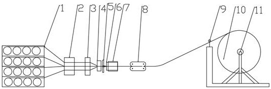
[0044] see Figure 1 to Figure 4 , the present invention provides a technical solution:

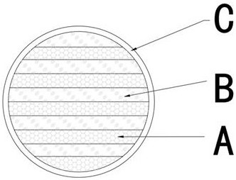
[0045] A composite anti-split continuous sucker rod, comprising a carbon fiber layer A, a glass fiber layer B, and a fabric covering layer C;

[0046] Both the carbon fiber layer and the glass fiber layer are wrapped inside the fabric covering layer; the carbon fiber layer and the glass fiber layer are provided with at least two layers, and the carbon fiber layer and the glass fiber layer are distributed parallel and alternately along the axial direction.

[0047] Further, the cross-section of the carbon fiber layers and glass fiber layers distributed parallel and alternately along the axial direction is circular, and the cross-section ratio is greater than or equal to 98%, and at the same time less than 99%. section ratio.

[0048] Further, the volume ratio of the carbon fiber layer to the glass fiber layer is 1 / 4-3 / 4.

[0049] Further, the cross section of the sucker rod is circular ...

Embodiment 2

[0070] see Figure 1 to Figure 4 , the present invention provides a technical solution:

[0071] A composite anti-split continuous sucker rod, comprising a carbon fiber layer A, a glass fiber layer B, and a fabric covering layer C;

[0072] Both the carbon fiber layer and the glass fiber layer are wrapped inside the fabric covering layer; the carbon fiber layer and the glass fiber layer are provided with at least two layers, and the carbon fiber layer and the glass fiber layer are distributed parallel and alternately along the axial direction.

[0073] Further, the cross-section of the carbon fiber layers and glass fiber layers distributed parallel and alternately along the axial direction is circular, and the cross-section accounts for more than 98%.

[0074] Further, the volume ratio of the carbon fiber layer to the glass fiber layer is 1 / 4-3 / 4.

[0075] Further, the cross section of the sucker rod is circular with a diameter of 10-30mm.

[0076] Further, the carbon fiber...

Embodiment 3

[0082] see Figure 1 to Figure 4 , the present invention provides a technical solution:

[0083] A composite anti-split continuous sucker rod, comprising a carbon fiber layer A, a glass fiber layer B, and a fabric covering layer C;

[0084] Both the carbon fiber layer and the glass fiber layer are wrapped inside the fabric covering layer; the carbon fiber layer and the glass fiber layer are provided with at least two layers, and the carbon fiber layer and the glass fiber layer are distributed parallel and alternately along the axial direction.

[0085] Further, the cross-section of the carbon fiber layers and glass fiber layers distributed parallel and alternately along the axial direction is circular, and the cross-section accounts for more than 98%.

[0086] Further, the volume ratio of the carbon fiber layer to the glass fiber layer is 1 / 4-3 / 4.

[0087] Further, the cross section of the sucker rod is circular with a diameter of 10-30mm.

[0088] see Figure 1 to Figure ...


PUM

PropertyMeasurementUnit
diameteraaaaaaaaaa
tensile strengthaaaaaaaaaa

Abstract

The invention discloses a composite anti-splitting continuous sucker rod and a preparation device and a preparation method. The composite anti-splitting continuous sucker rod comprises carbon fiber layers, glass fiber layers and a fabric coating layer; the carbon fiber layers and the glass fiber layers are coated in the fabric coating layer; and at least two carbon fiber layers and at least two glass fiber layers are provided, and are alternately distributed in parallel in the axial direction. Further, the sections of the carbon fiber layers and the glass fiber layers alternately distributed in parallel in the axial direction are circular. The multilayer parallel structure can fully exert the advantages of carbon fibers, so that the overall shearing strength of a rod body is improved, and the torsion resistance of the rod body is improved. Porous preforming and single-hole preforming mechanisms in preforming mechanisms realize axial uniform and parallel alternate distribution of the carbon fibers and high-modulus glass fibers. The composite anti-splitting continuous sucker rod is once molded through a pultrusion process, so that the product quality stability can be greatly improved, the production efficiency is high, the interlayer strength is high, and the layering cracking condition is prevented.

Description

technical field [0001] The invention relates to the technical field of oil production equipment in the petroleum industry, in particular to a composite anti-split continuous sucker rod, a preparation device and a preparation method. Background technique [0002] Due to the increasingly complex types of developed reservoirs, the continuous increase of well depth and the continuous deterioration of the well and mine environment, the problems of corrosion and eccentric wear have become problems that need to be solved urgently in the oil production process of oilfields. Because of its light weight, high strength and corrosion resistance, composite sucker rods have gradually replaced traditional metal sucker rods. The composite material sucker rods currently used mainly include two categories: glass fiber reinforced plastic sucker rods and carbon fiber reinforced composite continuous sucker rods. FRP sucker rods are manufactured by pultrusion process of glass fiber reinforced th...

Claims


Application Information

Patent Timeline
Patent Type & Authority Applications(China)
IPC IPC(8): E21B17/00E21B17/10B29C70/52B32B5/02B32B9/00B32B9/04B32B17/02B32B17/12B32B27/02B32B27/12B32B27/34B32B33/00
CPCE21B17/00E21B17/1071B29C70/521B29C70/525B32B5/02B32B5/26B32B9/047B32B17/067B32B27/12B32B33/00B32B2262/106B32B2262/101B32B2262/0269B32B2250/20B32B2307/54
Inventor 智勤功张中慧黄润晶杨斌郑强张方圆刘晓玲王慧莉徐建礼
Owner CHINA PETROLEUM & CHEM CORP
Why Eureka
Try Eureka