Vertical low-carbon condensation energy saver
An economizer, vertical technology, applied in steam/steam condensers, air heaters, fluid heaters, etc., can solve the problems of low temperature of water supply, waste of flue gas heat, low efficiency of hot water, etc., to reduce flow time, reduce water leakage, long residence time effect
- Summary
- Abstract
- Description
- Claims
- Application Information
AI Technical Summary
Problems solved by technology
Method used
Image

Examples
Embodiment 1
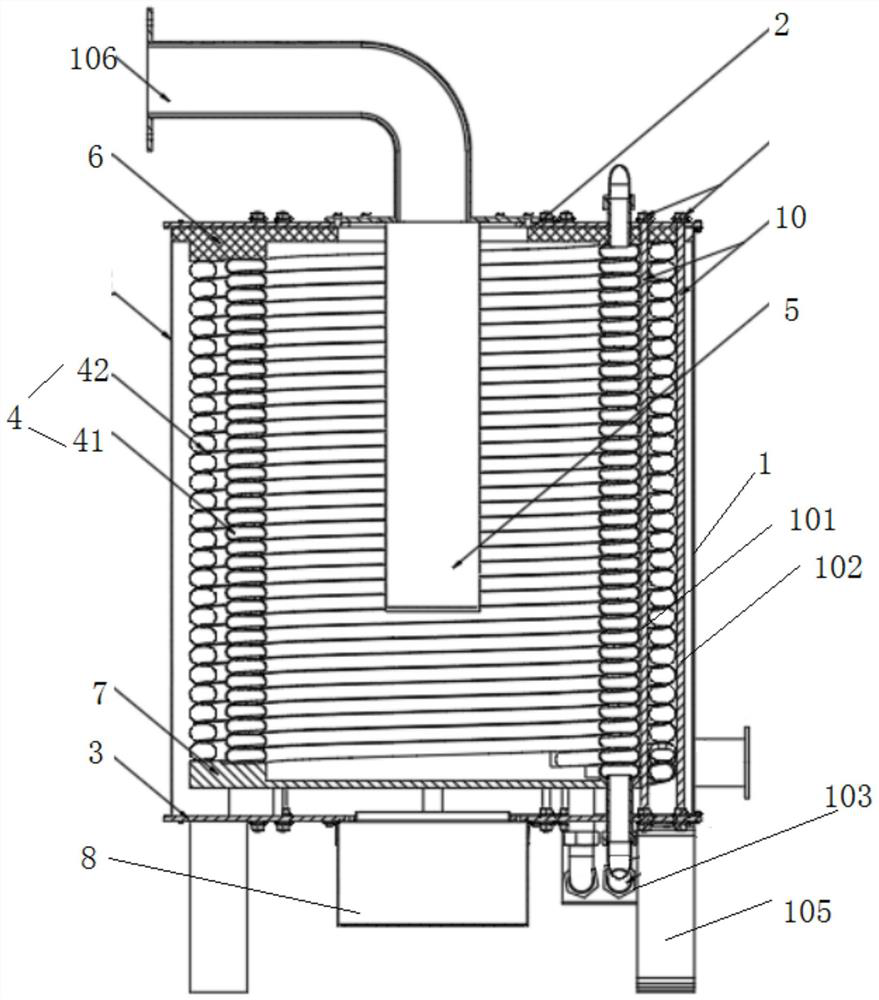
[0039] Such as Figure 1-8 As shown, a vertical low-carbon condensing economizer includes a housing 1, a front cover 2, a rear cover 3, a heat exchange coil 4 and a combustion assembly 5; the housing 1 is a cavity with openings at both ends as a whole body structure, the front cover 2 and the rear cover 3 are respectively arranged on both sides of the shell 1, the heat exchange coil 4 is set in the shell 1; the combustion assembly 5 is set in the heat exchange coil 4 in;
[0040]Based on the above structure, the heat exchange coil 4 is directly or indirectly heated by burning through the combustion assembly 5, so that the liquid in the heat exchange coil 4 can be heated rapidly to achieve the purpose of heat exchange;
[0041] The front cover 2 is provided with a main through hole 11 for the combustion assembly 5 to pass through, the first passage is arranged at the center of the front cover 2; the front cover 2 is provided with a second through hole group 12 , leading out p...
Embodiment 2
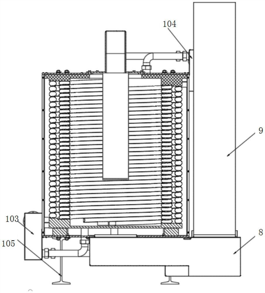
[0055] Based on the above-mentioned embodiment 1, in this embodiment, the vertical low-carbon condensation economizer also includes a smoke-water separator 8 and a smoke exhaust pipe 9, and the smoke-water separator 8 is directly connected to the back cover 3 through a pipeline. The gas outlet is connected, and the exhaust pipe 9 is communicated with the smoke-water separator 8. The height of the smoke exhaust pipe 9 is not less than the height of the overall economizer, so that the flue gas passing through the smoke gas separator will be in the smoke exhaust pipe 9. It will further condense when it is cold, and reduce the amount of harmful gas emitted.
[0056] Based on the above structure, the low-temperature flue gas will enter the smoke-water separator 8 through the rear cover plate 3 for separation, and the sulfur-containing liquid is stored in the smoke-water separator 8 for discharge.
[0057] The vertical low-carbon condensing economizer also includes a tie rod part 10...
Embodiment 3
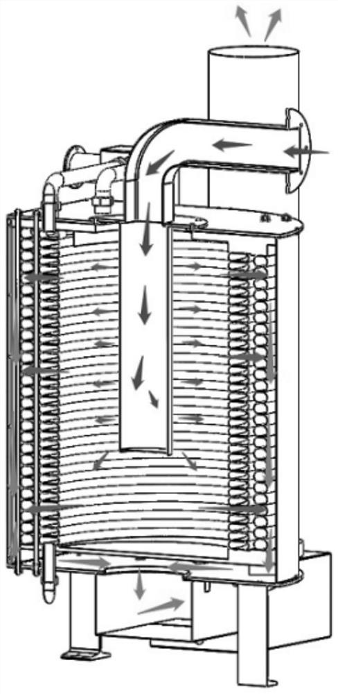
[0063] Such as Figure 9 As shown, based on the above-mentioned embodiment 1 or 2, in this embodiment, the first heat exchange pipeline 411 and the second heat exchange pipeline 412 are connected at intervals through gap cards, and the adjacent first heat exchange pipeline 411 and the second heat exchange pipeline 412 form the first flow cavity 107, and the third heat exchange pipeline 421 and the fourth heat exchange pipeline 422 are connected at intervals through gap cards, and the adjacent first The second flow chamber 108 is formed between the third heat exchange pipeline 421 and the fourth heat exchange pipeline 422, and the first flow chamber 107 and the second flow chamber 108 are not collinearly arranged;
[0064] Since both the inner coil 41 and the outer coil 42 have a spiral structure, the first flow chamber 107 and the second flow chamber 108 are staggered during manufacture. At this time, when the combustion assembly 5 is burning, The high-temperature flue gas fi...
PUM
 Abstract
Description
Claims
Application Information
 - R&D
- Intellectual Property
- Life Sciences
- Materials
- Tech Scout
- Unparalleled Data Quality
- Higher Quality Content
- 60% Fewer Hallucinations
Browse by: Latest US Patents, China's latest patents, Technical Efficacy Thesaurus, Application Domain, Technology Topic, Popular Technical Reports.
© 2025 PatSnap. All rights reserved.Legal|Privacy policy|Modern Slavery Act Transparency Statement|Sitemap|About US| Contact US: help@patsnap.com