Thermal power plant flue gas sampling system

A technology for flue gas sampling and thermal power plants, which is applied in sampling, sampling devices, measuring devices, etc. It can solve problems such as inaccurate sampling results, limited compressed air flow, large temperature difference between compressed air and flue gas, and achieves easy dredging, cleaning and sampling tube, accurate sampling results, and easy operation

Pending Publication Date: 2022-01-11
HUANENG LINYI POWER GENERATION CO LTD
View PDF0 Cites 1 Cited by
  • Summary
  • Abstract
  • Description
  • Claims
  • Application Information

AI Technical Summary

Problems solved by technology

[0006] 1. If the flue gas is mixed outside the flue, due to the sudden drop in temperature, the water vapor in the flue gas will condense, and the measured nitrogen oxides are easily soluble in water, and part of the nitrogen oxides will dissolve in the condensed water when the flue gas is mixed. , making the sampling results inaccurate
[0007] 2. If the flue gas is mixed in the flue, due to the large temperature difference between the compressed air and the flue gas, when the compressed air is ejected, the water vapor in the flue gas will also condense in the main pipe, and part of the nitrogen will be oxidized when the flue gas is mixed in the main pipe The nitrogen oxide content is dissolved in the condensed water, causing the nitrogen oxide content to decrease continuously during the flue gas mixing process, making the sampling results inaccurate
[0008] 3. The compressed air flow available on site is limited. In order to ensure that each sampling tube can generate negative pressure, the diameter of the sampling tube should not be too large. During sampling, each sampling tube may be blocked by smoke and dust, and the sampling tube is located in the flue. Unable to dredge during boiler operation
[0009] 4. When mixing in the main pipe of the sampling system, the space inside the main pipe is small, and it is difficult to cause the flue gas transported by each sampling pipe to rotate, collide, convect, and cannot achieve effective mixing. The measurement results are difficult to represent the flue gas on the entire flue section Component Concentration

Method used


Image

  • Thermal power plant flue gas sampling system
  • Thermal power plant flue gas sampling system

Examples


Embodiment Construction

[0032] The preferred embodiments of the present invention will be described in detail below in conjunction with the accompanying drawings, so that the advantages and features of the present invention can be more easily understood by those skilled in the art, so as to define the protection scope of the present invention more clearly.

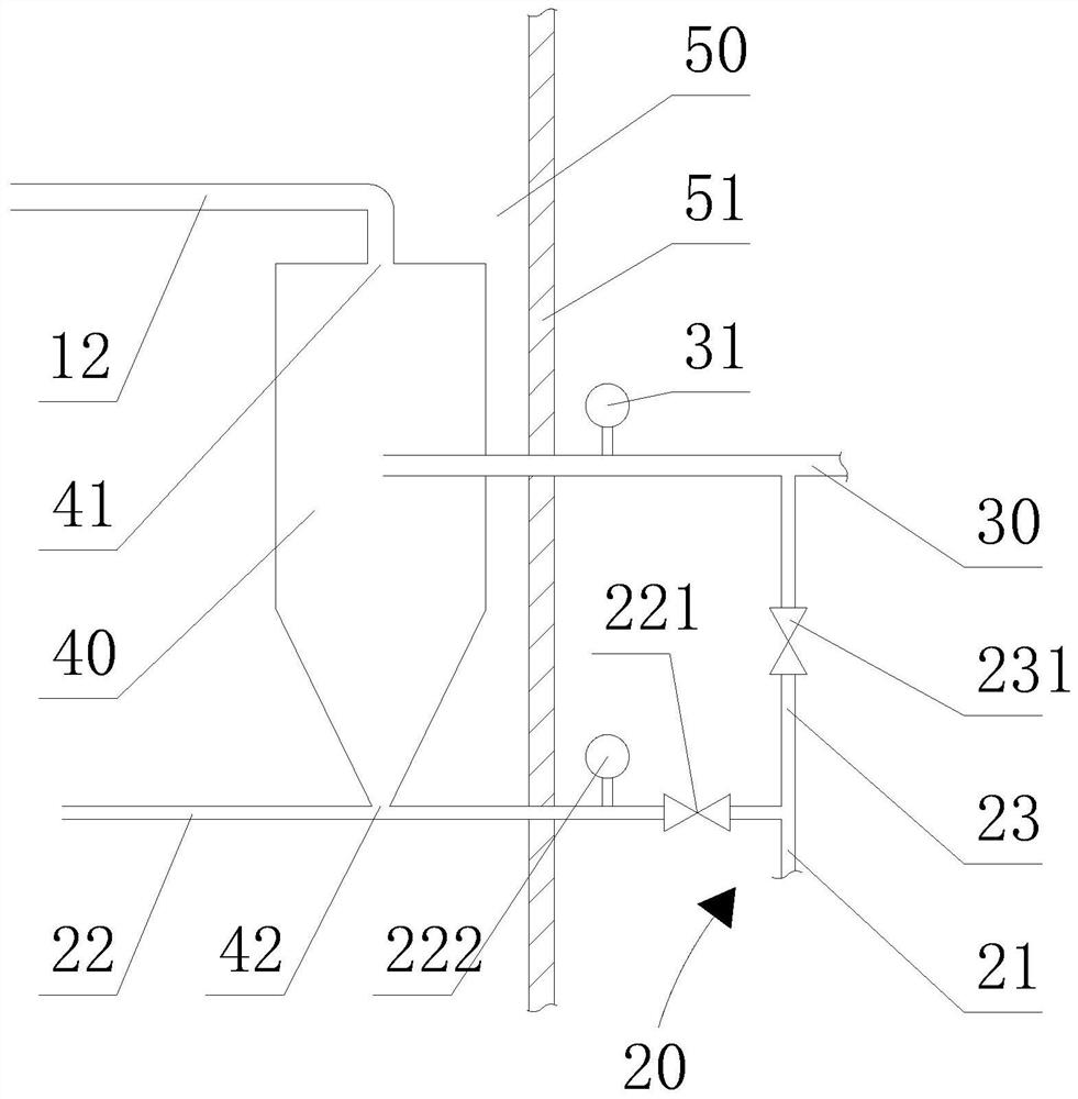
[0033] The up-down direction described in the present invention is figure 2 In the up and down direction, the flue gas in the flue in the present invention is along figure 2 flow in a top-down direction.

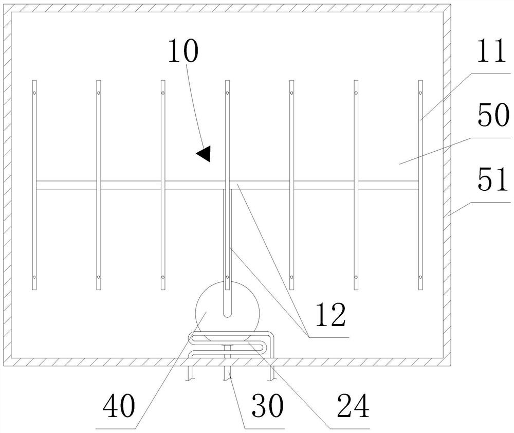
[0034] like Figure 1-2 As shown, the thermal power plant flue gas sampling system provided by the present invention includes: a sampling pipe 10, an air pipe 20, a probe outer sleeve 30, and a smoke mixing tank 40, wherein the sampling pipe 10 is arranged in the flue 50, and the sampling pipe 10 includes A plurality of sampling branch pipes 11 and a sampling main pipe 12, a plurality of sampling branch pipes 11 are arranged at intervals be...


PUM


Abstract

The invention provides a thermal power plant flue gas sampling system which comprises a sampling pipe, an air pipe, a probe outer sleeve and a flue gas mixing tank. The sampling pipe comprises the multiple sampling branch pipes arranged below the ammonia gas injection grid at intervals, multi-point sampling can be achieved, the first branch pipe of the air pipe is communicated with the flue gas mixing tank, negative pressure can be formed in the flue gas mixing tank, the smoke sample in the sampling pipe is sucked into the flue gas mixing tank to be mixed, the mixing space is large, the heating pipe panel is arranged on the main air pipe of the air pipe to heat compressed air, the flue gas mixing tank is arranged in the flue, condensate water can be prevented from being generated when the smoke sample is mixed, the sampling and mixing effect is good, and the sampling result is accurate. The probe outer sleeve penetrates through the flue wall and is inserted into the flue gas mixing tank, the second branch pipe is communicated with the probe outer sleeve, compressed air can be sprayed out from the probe outer sleeve, the flue gas mixing tank and the sampling pipe into the flue through the second branch pipe, the sampling pipe is convenient to dredge and clean, the structure is simple, and operation is convenient.

Description

technical field [0001] The invention relates to the technical field of flue gas sampling in thermal power plants, in particular to a flue gas sampling system in thermal power plants. Background technique [0002] Thermal power plants, referred to as thermal power plants, are factories that use combustibles (such as coal) as fuel to produce electricity. Standards are also constantly improving. In order to adapt to this standard, the control standard of nitrogen oxides in the flue gas denitrification control system of thermal power plants is also improving. [0003] At present, the flue gas denitrification control of thermal power plants usually uses the nitrogen oxide content detected by the sampling system as the control basis, and compares the deviation between the actual value and the set value to automatically adjust the amount of ammonia injection. Under the condition that the operation process and control logic remain unchanged, Whether the sampling of nitrogen oxides ...

Claims


Application Information

Patent Timeline
Patent Type & Authority Applications(China)
IPC IPC(8): G01N1/22G01N1/24
CPCG01N1/2258G01N1/24G01N2001/2261
Inventor 张瑾明
Owner HUANENG LINYI POWER GENERATION CO LTD
Why Eureka
Try Eureka