All-dielectric optical cable and laying method thereof
An all-dielectric and optical cable technology, which is applied in the field of optical cables, can solve the problems of not being able to effectively expand the types and applications of all-dielectric optical cables, and that the selection and structure of optical cables are relatively limited, so as to improve construction efficiency, save installation resources, and reduce contact probability. Effect
- Summary
- Abstract
- Description
- Claims
- Application Information
AI Technical Summary
Problems solved by technology
Method used
Image
Examples
Embodiment 1
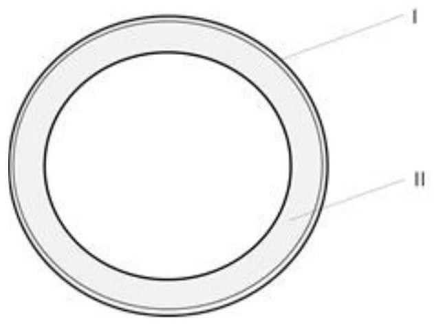
[0053] refer to figure 1 In this embodiment, grooves are arranged alternately on the outer side of the sheath, and the water lubricating layer is arranged in the grooves, and the layer-stranded optical core in the sheath adopts ordinary colored optical fiber.
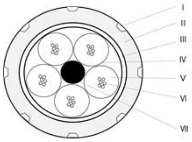
[0054] The structure of the all-dielectric optical cable of this embodiment is as follows: image 3 As shown, the number of cores of the optical cable is 30, the number of strands is 5, the number of optical fiber cores in each sleeve is 6 cores, the water lubricating layer I is water-soluble resin, and the sheath II is MDPE , the water-blocking tape III is a sodium polyacrylate coated tape, the sleeve IV is a PBT loose tube, the water-blocking filler V is ointment, the optical fiber VI is a colored optical fiber, and the central strength member VII is GRP.
[0055] Wherein, the water lubricating layer such as figure 1 As shown, it is continuous in the longitudinal direction of the sheath and alternately and symmetri...
Embodiment 2
[0060] refer to figure 1 In this embodiment, grooves are arranged alternately on the outer side of the sheath, and the water lubricating layer is arranged in the grooves, and the layer-stranded optical core in the sheath adopts ordinary colored optical fiber.
[0061] The structure of this embodiment is as Figure 4 As shown, the number of cores of the optical cable is 72, the number of strands is 6, the number of optical fiber cores in each sleeve is 12 cores, the water lubricating layer I is water-soluble resin, and the sheath II is HDPE , the water-blocking tape III is a sodium polyacrylate coated tape, the sleeve IV is a PBT loose tube, the water-blocking filler V is a water-blocking yarn, the optical fiber VI is a colored optical fiber, and the central reinforcement Item VII is GRP.
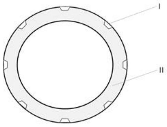
[0062] Wherein, the water lubricating layer such as figure 2 As shown, it is arranged vertically and continuously alternately symmetrically with the sheath, the number of the water lubri...
Embodiment 3
[0067] refer to figure 1 In this embodiment, grooves are arranged alternately on the outer side of the sheath, and the water lubricating layer is arranged in the grooves, and the layer-stranded optical core in the sheath adopts an optical fiber ribbon.
[0068]The structure of this embodiment is as figure 2 As shown, the number of cores of the optical cable is 120, the number of strands is 5, the number of optical fiber ribbons in each loose tube is 2, the number of optical fibers in the optical fiber ribbon is 12f, and the water lubricating layer I is a water-soluble resin. The sheath II is MDPE, the water blocking tape III is a sodium polyacrylate coated tape, the sleeve IV is a PBT loose tube, the V is an optical fiber ribbon, and the water blocking filler VI is ointment , the central reinforcement VII is GRP.
[0069] Wherein, the water lubricating layer such as figure 2 As shown, it is arranged vertically and continuously alternately symmetrically with the sheath, th...
PUM
| Property | Measurement | Unit |
|---|---|---|
| Kinematic viscosity | aaaaa | aaaaa |
| Diameter | aaaaa | aaaaa |
| Kinematic viscosity | aaaaa | aaaaa |
Abstract
Description
Claims
Application Information
 - R&D
- Intellectual Property
- Life Sciences
- Materials
- Tech Scout
- Unparalleled Data Quality
- Higher Quality Content
- 60% Fewer Hallucinations
Browse by: Latest US Patents, China's latest patents, Technical Efficacy Thesaurus, Application Domain, Technology Topic, Popular Technical Reports.
© 2025 PatSnap. All rights reserved.Legal|Privacy policy|Modern Slavery Act Transparency Statement|Sitemap|About US| Contact US: help@patsnap.com


