Sealing structure and sealing method of plastic sealing new energy high-voltage direct-current relay

A high-voltage DC, sealed structure technology, applied in relays, electromagnetic relays, electromagnetic relay details, etc., can solve the problems of uneven dispensing, increase the fluidity of epoxy glue, easy to lack glue, etc., to avoid lack of glue, improve Homogeneous, fluidity-increasing effect

Pending Publication Date: 2022-01-11
安徽中骄创新技术发展有限公司
View PDF18 Cites 0 Cited by
  • Summary
  • Abstract
  • Description
  • Claims
  • Application Information

AI Technical Summary

Problems solved by technology

Another object of the present invention is to provide a sealing method for plastic-sealed new energy high-voltage DC relays. By using an electric heating device to cure epoxy glue, the fluidity of epoxy glue before curing is increased, and uneven dispensing is further solved. The problem of lack of glue

Method used


Image

  • Sealing structure and sealing method of plastic sealing new energy high-voltage direct-current relay
  • Sealing structure and sealing method of plastic sealing new energy high-voltage direct-current relay
  • Sealing structure and sealing method of plastic sealing new energy high-voltage direct-current relay

Examples


Embodiment 1

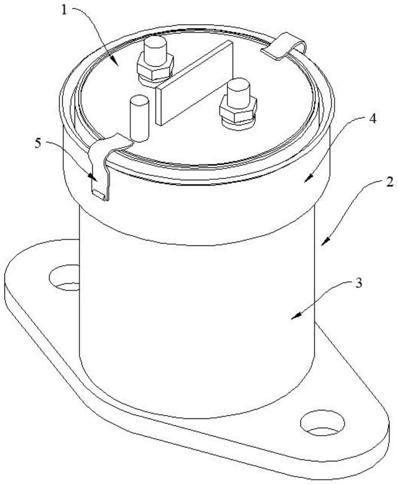
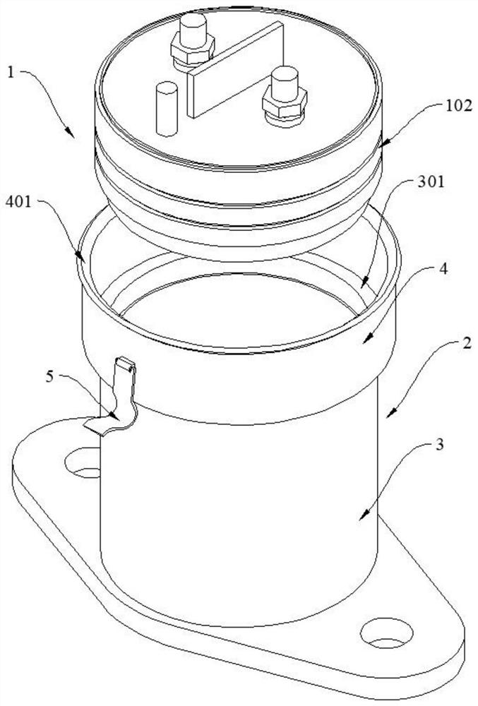
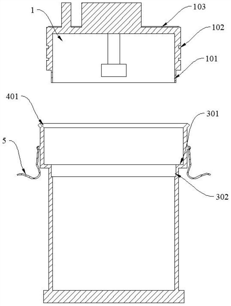
[0035] see Figure 1-Figure 2 As shown, the present invention is a sealing structure of a plastic-sealed new energy high-voltage DC relay, including an upper case 1 and a lower case 2, the upper case 1 is a circular groove with the opening facing downward, and the circumference of the upper case 1 There are two annular grooves 102 on the side. On the one hand, the annular grooves 102 can enhance the connection strength between the upper and lower shells, and on the other hand, increase the filling amount of epoxy glue to improve the sealing performance of the upper and lower shells.

[0036] see Figure 1-Figure 5 The shown lower casing 2 includes a first casing 3 and a second casing 4, the diameter of the second casing 4 is greater than the diameter of the first casing 3, and the lower end surface of the second casing 4 is connected to the bottom surface of the first casing 3. The upper end surface is fixedly connected, and a first step 301 is formed at the joint between the...

Embodiment 2

[0045] see Figure 2-Figure 4 As shown, the lower end surface of the upper housing 1 is fixedly connected with the limiting ring 101, and the upper end surface of the first housing 3 is provided with a limiting groove 302, and the limiting ring 101 is slidably matched with the limiting groove 302 to ensure the uniformity of the glue injection gap. , At the same time, it forms a second barrier to prevent the epoxy glue from losing to the inside of the shell, so as to avoid the loss of epoxy glue into the shell cavity, resulting in local lack of glue. The inner wall of the limiting ring 101 and the inner wall of the upper housing 1 are on the same curved surface. After the limiting ring 101 is matched with the limiting groove 302, the inner wall of the limiting ring 101 and the inner wall of the first housing 3 are also on the same curved surface, ensuring The installation gap of the device inside the housing, while avoiding collisions with the components during the installation...


PUM


Abstract

The invention discloses a sealing structure and a sealing method of a plastic sealing new energy high-voltage direct-current relay, and relates to the technical field of high-voltage direct-current relays. The structure comprises an upper shell and a lower shell, wherein a plurality of annular grooves are formed in the peripheral side surface of the upper shell; the lower shell comprises a first shell and a second shell, and a first step is formed at the joint of the second shell and the first shell; the inner side wall of the second shell is in clearance fit with the peripheral side surface of the upper shell to form a glue injection clearance; a plurality of spring buckles are hinged to the peripheral side face of the second shell and connected with the upper surface of the upper shell in a clamped mode, the lower end face of the upper shell is fixedly connected with a limiting ring, a limiting groove is formed in the upper end face of the first shell, and the limiting ring is in sliding fit with the limiting groove. Through arrangement of the spring buckles, the connection strength between the upper shell and the lower shell is enhanced, through sliding fit of the limiting rings and the limiting grooves, the uniformity of glue injection gaps is guaranteed, glue dispensing is more uniform, and the sealing effect is improved.

Description

technical field [0001] The invention belongs to the technical field of high-voltage direct-current relays, and in particular relates to a sealing structure of a plastic-sealed new-energy high-voltage direct-current relay and a sealing method of a plastic-sealed new-energy high-voltage direct-current relay. Background technique [0002] The relay is an electronic control device, which consists of a control system (also known as an input circuit) and a controlled system (also known as an output circuit). It is usually used in an automatic control circuit. It actually uses a smaller current to control a larger current. A kind of "automatic switch". Therefore, it plays the role of automatic adjustment, safety protection and conversion circuit in the circuit. High-voltage DC relays are the core components of new energy vehicles, and are widely used in the circuit switching control in vehicles, including all electrical appliances such as wipers, windows, and lights. During the o...

Claims


Application Information

Patent Timeline
Patent Type & Authority Applications(China)
IPC IPC(8): H01H50/02H01H49/00
CPCH01H50/023H01H50/02H01H49/00
Inventor 张洪涛
Owner 安徽中骄创新技术发展有限公司
Why Eureka
Try Eureka