
Capacitor clamping H-type boost converter based on switch inductor/capacitor

A technology of boost converter and capacitor clamping, which is applied in the direction of conversion equipment without intermediate conversion to AC, photovoltaic power generation, etc., can solve the problems of large voltage stress, limited voltage gain, and limited gain of power devices, and achieve low voltage stress , reduce conduction loss, increase the effect of voltage gain

Pending Publication Date: 2022-01-14
NANJING UNIV OF SCI & TECH
View PDF0 Cites 2 Cited by
  • Summary
  • Abstract
  • Description
  • Claims
  • Application Information

AI Technical Summary

Problems solved by technology

The boost converter based on coupled inductor achieves higher voltage gain by changing the winding ratio of coupled inductor, but due to the influence of leakage inductance, it is necessary to introduce a clamp circuit to suppress the turn-off voltage peak of the switching tube; the boost converter based on the switching inductor unit The voltage gain range of the voltage converter has been expanded, but the voltage stress of the power device is still large and the gain is limited; the voltage stress of the switching device in the boost converter based on the switched capacitor unit is small, but the voltage gain is limited, which is only the traditional Boost converter. twice as much

Method used


Image

  • Capacitor clamping H-type boost converter based on switch inductor/capacitor
  • Capacitor clamping H-type boost converter based on switch inductor/capacitor
  • Capacitor clamping H-type boost converter based on switch inductor/capacitor

Examples


Embodiment Construction

[0017] The present invention will be further described below in conjunction with the accompanying drawings and specific embodiments.

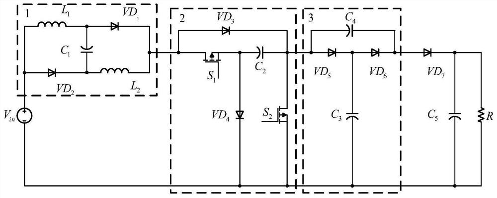
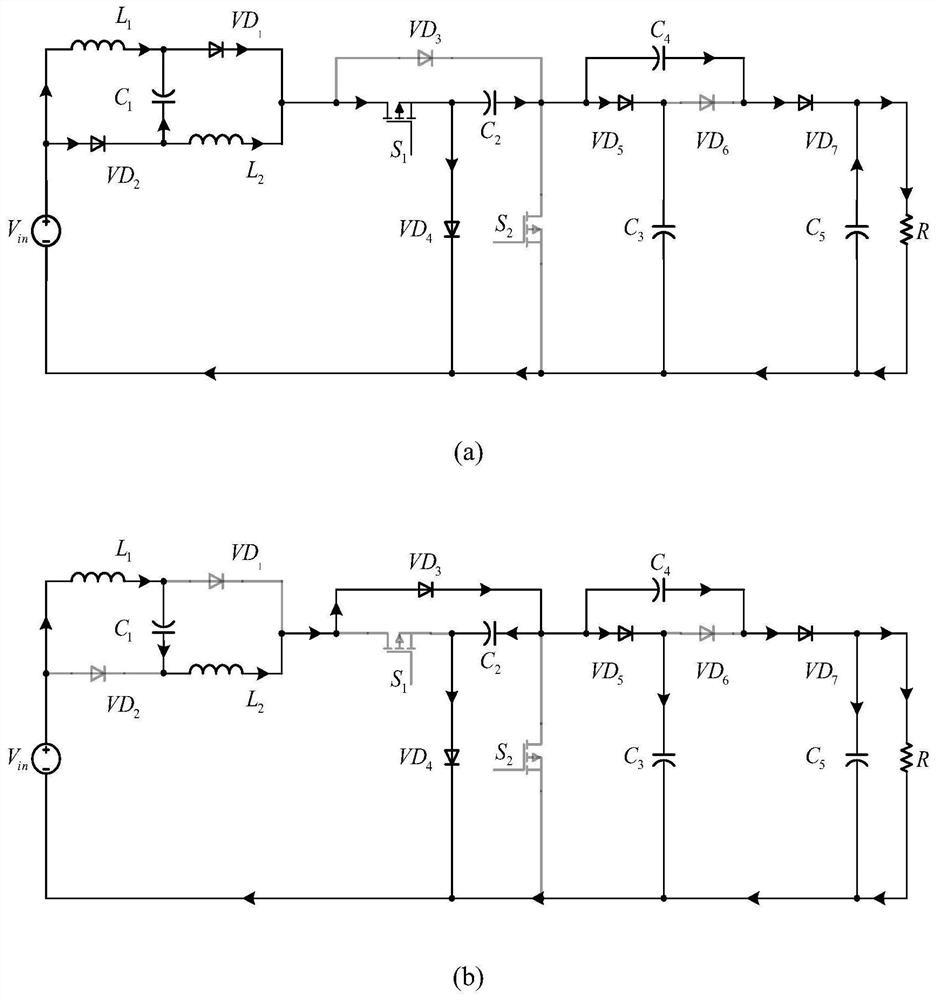
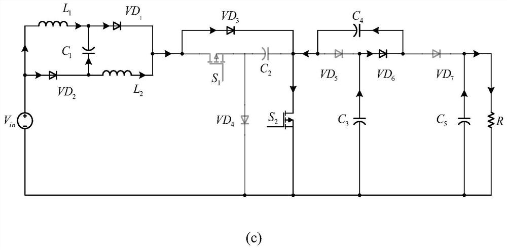
[0018] Combine figure 1 The present invention proposes a capacitance clamp H-type boost converter based on a switching inductance / capacitor, including input source V in , First inductance L 1 , Second inductance L 2 First diode VD 1 , Second diode VD 2 , Third diode VD 3 , Fourth diode VD 4 , Fifth diode VD 5 , Sixth diode VD 6 , Seventh diode VD 7 , First power switch tube S 1 , Second power switch tube S 2 , First capacitive C 1 , Second capacitance C 2 , Third capacitance C 3 , Fourth capacitive C 4 , Fifth capacitor C 5 , Load R; where input source V in Positive electrode second diode VD 2 The anode, the first inductor L 1 One end, second diode VD 2 Anode, first inductance L 1 The other end of the first diode VD 1 The anode, the second inductance L 2 One end, second diode VD 2 Cathode, second inductance L 2 On the other end of the first diode...


PUM


Abstract

The invention discloses a capacitor clamping H-type boost converter based on a switch inductor / capacitor, which belongs to the field of power electronic converters. On the basis of a Boost converter, the converter is combined with an improved switch inductor unit consisting of an inductor, a capacitor and a diode, a capacitor clamping H-shaped structure consisting of power switch tubes and the capacitor, and a switch capacitor unit consisting of the diode and the capacitor, so that the switch-on and switch-off of the two power switch tubes are controlled; the on-off condition of the diode and the connection mode of the inductor and the capacitor in the circuit can be changed, so that the effect of improving the voltage gain is achieved. The occurrence of a limit duty ratio is avoided while high voltage gain is realized, the safety and the reliability of the circuit are improved, the voltage stress borne by the switch device is relatively low, the switch-on loss of the switch device is reduced, and the converter is suitable for new energy power generation systems such as fuel cells and photovoltaic cells.

Description

Technical field [0001] The present invention belongs to the field of power electronically converters, and more particularly to a capacitance clamping H-type boost converter based on a switching inductance / capacitor. Background technique [0002] Energy is an important substance foundation of human society with survival and development, and has an important role in promoting national economic development and overall national strength. However, with the rapid development of the world economy and technology, traditional energy consumption is increasing, and environmental pollution caused by energy shortage and excessive use of energy has gradually become two major issues that threaten human survival and development. Develop efficient, economical, clean, sustainable energy has become a core proposition of human Duhui sustainable development. [0003] In recent years, hydrogen can be used as a new type of energy in the future green and sustainable development. It has been widely ref...

Claims


Application Information

Patent Timeline
IPC IPC(8): H02M3/04H02M3/07
CPCH02M3/04H02M3/07Y02E10/56
Inventor 周礼锋沈致远戚志东徐胜元张扬孙成硕
Owner NANJING UNIV OF SCI & TECH
Learn More