Coupler for microwave pyrolysis systems

A coupling and pyrolysis reactor technology, applied in the field of pyrolysis, can solve the problems of stub and stub shell mechanical damage, system loss, etc.

Pending Publication Date: 2022-01-14
파이로웨이브인크
View PDF9 Cites 2 Cited by
  • Summary
  • Abstract
  • Description
  • Claims
  • Application Information

AI Technical Summary

Problems solved by technology

The system then loses its ability to change the tuner impedance
Also, forcing the stub to move or out may cause mechanical damage to the stub and the stub housing

Method used


Image

  • Coupler for microwave pyrolysis systems
  • Coupler for microwave pyrolysis systems
  • Coupler for microwave pyrolysis systems

Examples


Embodiment Construction

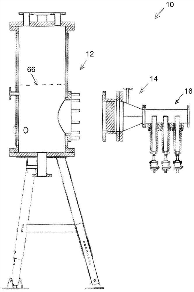
[0058] figure 1 One embodiment of a microwave pyrolysis system 10 is shown that includes a reactor or vessel 12 , a coupling 14 and a tuner 16 . It should be understood that the tuner 16 may be connected to a microwave source or microwave generator (not shown), either directly or via a microwave waveguide. In the illustrated embodiment, a tuner 16 is used to direct the microwaves emitted by the microwave generator to the coupler 14 . The tuner 16 may also be used to adjust the power of the microwave energy delivered to the coupler 16 and thus to the reactor 12 . Coupling 14 is used to propagate microwaves from tuner 16 into reactor 12 . Reactor 12 is configured to receive therein the product to be pyrolyzed, which product is heated by microwave heating.

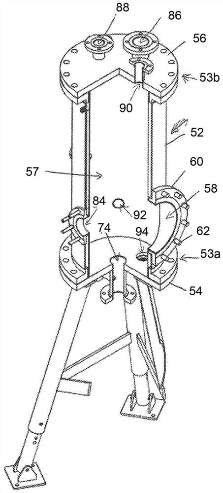
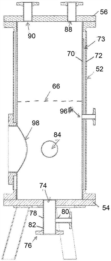
[0059] refer to Figure 2 to Figure 5 , an embodiment of the reactor 12 is shown. Reactor 12 is configured to perform chemical and / or physical reactions therein under the action of microwave energy.

[0060] In the illu...


PUM

PropertyMeasurementUnit
diameteraaaaaaaaaa

Abstract

There is described a coupler for propagating microwaves into a microwave pyrolysis reactor, the coupler comprising: an elongated hollow body for propagating the microwaves, the elongated hollow body extending between a receiving end for receiving the microwaves and a transmitting end mountable to the microwave pyrolysis reactor for propagating the microwaves therein, the receiving end having a rectangular cross-sectional shape and the transmitting end having a circular cross-sectional shape, a shape of the elongated allow body being designed so as to convert a transverse (TE) mode of propagation for the microwaves at the receiving end thereof into a linearly polarized (LP) mode of propagation for the microwaves at the transmitting end thereof; and a barrier body inserted into the hollow body for isolating the receiving end of the elongated hollow body from the transmitting end thereof.

Description

technical field [0001] The present invention relates to the field of pyrolysis, and more particularly, to a coupler for a microwave pyrolysis system. Background technique [0002] Pyrolysis of products such as biomass and plastics is usually carried out in reactors under anaerobic conditions (ie in the absence of oxygen) with the addition of energy. There are generally three reaction products: oil, natural gas, and carbon black. In most cases, the pyrolysis process is tuned to maximize oil yield, since it is often of greatest value as a source of chemicals or fuel. [0003] Conventional heating sources for pyrolysis typically include the combustion of fuel gas to produce a flame and hot combustion gas or resistive heating elements. In such conventional pyrolysis systems, the outer surface of the reactor is heated so that heat can be transferred to the product to be pyrolyzed through the reactor wall via heat conduction. [0004] However, at least some conventional pyrolys...

Claims


Application Information

Patent Timeline
Patent Type & Authority Applications(China)
IPC IPC(8): H01P5/12B01J19/12H01P1/163
CPCH01P1/207B01J19/126B01J6/008C10B19/00C10B53/07C10B53/02
Inventor 乔斯林·杜塞让菲利普·拉维奥莱特
Owner 파이로웨이브인크
Why Eureka
Try Eureka